EE 330 Lecture 2026 11 10 Ch7 Amp#3
Overview
The lecture develops small-signal analysis for MOSFET and BJT amplifiers, starting with DC bias, operating-region checks, and the construction of AC equivalent circuits. It derives MOSFET and BJT T models from their pi models and shows when each representation simplifies gain calculations, especially when a source or emitter resistor is present.
Key takeaways
- Large coupling capacitors are open circuits for DC bias analysis and approximate shorts for midband small-signal analysis, so each amplifier must be reduced separately for the two operating conditions.
- A MOSFET with its gate tied to its drain through a resistor has V_G = V_D at DC when gate current is zero; with the source grounded, V_DS = V_GS, which satisfies the saturation inequality whenever V_GS exceeds V_T.
- The MOSFET T model replaces the gate-to-source small-signal relationship with an equivalent resistance of 1/g_m, making source-resistor circuits easier to solve.
- A source or emitter voltage drop means the device control voltage is not simply the input voltage; for a MOSFET, v_gs = v_g − v_s, and ignoring v_s can cause a large gain error.
- For a common-emitter BJT, the example's β = 100 and I_B ≈ 0.023 mA give I_C ≈ 2.3 mA and V_C ≈ 3.1 V, while the negative gain sign indicates phase inversion at the collector.
- Choose between pi and T models based on topology rather than device identity alone: the T model is often clearer with source/emitter components, while the pi model is usually simpler when that terminal is grounded.
Chapters
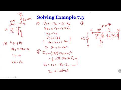
- The example gives a MOSFET threshold voltage of 1.5 V and Early voltage of 50 V, so the small-signal model must include output resistance r_o.
- Large coupling capacitors act as open circuits for DC and approximately as shorts for the AC small-signal circuit.
- For the DC bias calculation, the input and load R_L are disconnected by the coupling capacitors.
- MOSFET saturation requires V_GS > V_T and V_DS ≥ V_GS − V_T.
- With no DC gate current, the gate-to-drain resistor has no DC voltage drop, so V_G = V_D and V_GS = V_DS when the source is grounded.
- Use V_D = 15 V − R_D I_D together with the saturation current equation to solve for I_D; the stated example result is approximately 1.06 mA.
- Replace the MOSFET with its small-signal model containing the controlled current source g_m v_gs and r_o.
- For AC analysis, the DC supply becomes ground and the large coupling capacitors become short circuits.
- Connect R_D, R_L, and r_o at the drain, and retain the gate-to-drain resistor because it can carry AC current even though the MOSFET gate draws no current.
- Combine R_D, R_L, and r_o into the equivalent drain resistance R_L′ = R_D ∥ R_L ∥ r_o.
- Write a KCL equation at the drain, including current through the gate-to-drain resistor and the controlled source g_m v_gs.
- For the grounded-source example, v_gs equals the input small-signal voltage; solve for v_o as a function of v_in, then define gain as A_v = v_o/v_in.
- The MOSFET pi model is straightforward when the source is grounded, but can make circuits with source-side components harder to analyze.
- The T model is an algebraic transformation of the pi model intended to simplify particular circuit topologies, not a different physical device.
- The lecture applies the same model-conversion idea to both MOSFETs and BJTs.
- The derivation duplicates the controlled current source g_m v_gs in series, then connects the corresponding branches without changing the circuit behavior.
- The gate-to-source voltage and controlled current give the equivalent resistance r_s = 1/g_m.
- The resulting T-shaped small-signal representation preserves the MOSFET's zero gate-current property; r_o can be added afterward.
- In the common-gate circuit, the gate is AC-grounded, the input is applied at the source, and R_D connects the drain to AC ground.
- The pi-model gain follows from v_o = −g_m v_gs R_D; because the gate is grounded, v_gs = −v_in and the voltage gain is positive.
- The T model also works, but this grounded-gate example does not showcase its main advantage because there is no source resistor to simplify.
- A second MOSFET example includes a resistor R_S from source to ground and an AC input at the gate, with a separate DC bias source.
- In the pi model, v_gs is not equal to v_in: the source voltage rises by the current through R_S, so treating the two voltages as identical gives a substantially incorrect result.
- The T model makes the 1/g_m element and R_S a clear series path, allowing a direct voltage-divider or current calculation.
- Use the MOSFET T model when a resistor or other component is connected at the source and complicates the pi-model equations.
- When the source is directly grounded, the pi model is usually more direct.
- The model choice is a problem-solving convenience: either representation is valid if its circuit connections are handled correctly.
- The lecture introduces the BJT pi model, which includes r_π and the controlled collector-current source g_m v_be.
- Unlike a MOSFET gate, a BJT base draws current, so base-current relationships must be included in emitter-side calculations.
- The BJT T model is especially useful when a component is connected at the emitter.
- The derivation adds matching controlled-current branches and connects their intermediate nodes, following the MOSFET T-model transformation.
- The emitter-side resistance combines r_π with the 1/g_m contribution; the exact relationship is tied to β and the emitter current.
- For a BJT, I_E = I_C + I_B = (β + 1)I_B, unlike a MOSFET where gate current is zero.
- For the DC example, a 3 V bias through 100 kΩ and a 0.7 V base-emitter drop gives I_B ≈ 0.023 mA.
- With β = 100, I_C ≈ 2.3 mA; a 10 V supply and 3 kΩ collector resistor give V_C ≈ 3.1 V.
- In the AC pi model, the base voltage is set by the divider r_π/(r_π + R_B), and the collector output follows v_o = −g_m v_be R_C.
- The AC input rides on the DC base bias, while the small-signal base-emitter voltage v_be is only the changing component used in the gain model.
- The common-emitter gain includes a negative sign, so the collector AC waveform is inverted relative to the input.
- The output waveform is superimposed on the collector's DC operating voltage, illustrating the distinction between bias level and signal swing.
- The final example is a PNP common-base stage: the base is grounded for AC, the input is coupled to the emitter, and the collector has a 5 kΩ resistor.
- For DC, the 10 V supply, 10 kΩ emitter resistor, and 0.7 V base-emitter drop give I_E ≈ 0.93 mA.
- The resulting DC current is used to determine g_m and the small-signal model parameters before comparing pi-model and T-model AC circuits.
- For the PNP AC circuit, the DC sources become AC ground and the input coupling capacitor becomes a short; the base remains grounded.
- The pi-model and T-model representations both yield the common-base gain relation, with the polarity of v_be determining whether the output is in phase with the input.
- The practical rule is to use a T model when an NPN emitter or MOSFET source has a component connected to it; use the pi model when that terminal is grounded.
Transcript excerpt
0:00 Okay. So, we're going to continue with our chapter 7 uh contents. So today we're going to go do a few more examples of real shape how we can solve the small signal uh problems for MOSFET and PC and then we're going to uh derive another model uh to show that for certain circuits another model called T model will be better suited uh to solve the problem. So let's start with uh looking at a example. Um so in this example uh you guys can see we're given a couple of the parameters for mouse. um the treasure voltage given 1.5 volts
0:50 K W and also know that even VA is 50 volt which means so when you see this number you know that you want to include the um the resistance in the output R so if this is not given the cost to section Y is uh and then what I also saying is that coupling capacitors And then as this this capacitor call they're called coupling coupling means you you make the AC connect. So so just basically couples AC to the circuit it's couples capacitors uh it said that capacitors are fairly large means when omega will approach one will approach zero the C is fairly
1:39 large. So uh in that sense that this circuit we can look at uh from DC uh operation uh and then do as operation because we want to find the P of the voltage how much voltage in regards to the voltage. So in order to find that we suddenly have to go through the small circuit within the small. So that is something we have to do uh from the DC operation. So we'll start with this operation and then once we get that then we'll go move on to the small
This is the start of the transcript. Save this video free for the whole transcript, searchable and time-coded.
In this course
Related notes
Summary, takeaways, and chapters were generated by AI from the video's transcript and may contain errors. The video belongs to its creator, Wireless Power Transfer.