EE 330 Lecture 2026/9/22 Ch4 #3
Overview
The lecture develops practical diode analysis from ideal, constant-voltage, and Shockley models through Zener regulation and small-signal resistance. Worked examples use a 25 mV thermal voltage to calculate diode currents and voltage sensitivity, including a three-diode circuit whose output changes about 9.5 mV when a 10 V supply varies by 1 V, and a Zener regulator whose output depends on series resistance and load current.
Key takeaways
- The diode small-signal resistance is rd = VT / ID, so at VT = 25 mV and ID = 0.93 mA, rd is about 27 ohms.
- In a 10 V, 10 kΩ diode circuit, a 1 V supply ripple produces only about 2.7 mV of diode-voltage variation because the diode's 27-ohm incremental resistance is much smaller than the series resistor.
- Three forward-biased diodes at about 0.7 V each create a nominal 2.1 V reference; with a 1 kΩ feed resistor, a ±1 V supply change produces about ±9.5 mV of output variation.
- A Zener regulator maintains its output only while enough current remains through the Zener to keep it in breakdown; excessive load current causes the output voltage to collapse.
- For a Zener specified as 6.8 V at 5 mA with RZ = 20 ohms, the model's reference voltage is 6.7 V, not 6.8 V, because the dynamic-resistance drop must be subtracted.
Chapters
- The midterm announcement is corrected to Tuesday after a mistaken assumption that Monday was a holiday.
- The lecture distinguishes ideal diodes, with zero forward drop and no reverse current, from the constant-voltage model, which uses about 0.7 V forward drop.
- The Shockley or SPICE model describes current exponentially and is more appropriate when diode behavior needs greater accuracy.
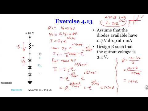
- For three identical series diodes with a total forward voltage of 2.4 V, each diode operates at about 0.8 V.
- Using a reference point of 0.7 V at 1 mA and thermal voltage VT = 25 mV, the exponential diode equation predicts about 55 mA at 0.8 V.
- With a 10 V supply, the series resistor is approximately (10 - 2.4 V) / 55 mA, or about 140 ohms.
- Unlike an ordinary diode, a Zener diode is designed to operate in reverse breakdown rather than being damaged by it.
- Below the Zener breakdown voltage, reverse current is approximately zero; in breakdown, voltage stays nearly constant as current rises.
- The practical Zener model represents the breakdown region with a reference voltage VZ0 in series with dynamic resistance RZ.
- A series resistor limits Zener current because breakdown can otherwise produce a large current and damage the diode.
- When a load is connected in parallel with the Zener, source current divides between load current IO and Zener current.
- If the load draws more current than the source-and-resistor network can provide while maintaining breakdown, the Zener voltage falls and regulation is lost.
- Choosing the series resistor involves a tradeoff: too small risks excessive no-load Zener current, while too large limits the current available to the load.
- Small-signal analysis estimates how small changes in supply voltage or component values affect a diode circuit around its DC operating point.
- Linearizing the Shockley equation around the bias point gives the incremental diode resistance rd = VT / ID.
- With VT = 25 mV, the resistance depends on the DC diode current, so the bias current must be calculated before using the small-signal model.
- The diode operating point is the intersection of the diode current-voltage curve and the circuit load line.
- A small supply change moves the operating point along the load line, producing a small change in diode voltage and current.
- The small-signal resistance represents the local slope of the diode curve near that operating point.
- The example uses a 10 V DC supply with a 1 V-amplitude, 60 Hz sinusoidal ripple, a 10 kΩ resistor, and a diode with a 0.7 V drop at 1 mA.
- Ignoring ripple first gives a DC current of (10 - 0.7 V) / 10 kΩ = 0.93 mA.
- The resulting small-signal resistance is about 25 mV / 0.93 mA = 27 ohms.
- Voltage division between 10 kΩ and 27 ohms gives about 2.7 mV of diode-voltage variation for a 1 V supply variation.
- The calculated 2.7 mV is the amplitude of the diode-voltage change around its 0.7 V DC operating point.
- The 60 Hz frequency does not affect this resistive small-signal calculation; the input amplitude determines the calculated variation.
- Doubling the input ripple amplitude from 1 V to 2 V approximately doubles the predicted diode variation to 5.4 mV.
- Three series diodes, each dropping about 0.7 V, provide a nominal 2.1 V output.
- The example uses a 10 V supply and a 1 kΩ series resistor, then tests a ±1 V supply variation, equivalent to 10%.
- The circuit is analyzed first without a load to isolate how the diode string responds to supply changes.
- At the nominal 2.1 V output, the 1 kΩ resistor supplies (10 - 2.1 V) / 1 kΩ = 7.9 mA.
- Each diode has an estimated small-signal resistance of about 25 mV / 7.9 mA, or 3.2 ohms; the three diodes total about 9.6 ohms.
- A ±1 V supply change produces about ±9.5 mV across the diode string, leaving the output near 2.1 V despite a 10% supply variation.
- Connecting a 1 kΩ load across the nominal 2.1 V output draws about 2.1 mA.
- If the series-resistor current remains 7.9 mA under the initial fixed-output assumption, diode-string current falls to about 5.8 mA.
- That reduced diode current changes the diode voltage, so the original 2.1 V assumption is no longer self-consistent and requires a revised calculation.
- For a 6.8 V Zener regulator, a very large load resistance draws little current and leaves the output close to 6.8 V.
- A near-short-circuit load pulls the output toward 0 V because the Zener cannot maintain its breakdown voltage under excessive load demand.
- The example considers a supply varying from 9 V to 11 V and emphasizes that both source variation and load resistance affect the output.
- The equivalent circuit replaces the Zener with a reference voltage VZ0 in series with dynamic resistance RZ.
- The model equation is VZ = VZ0 + IZ RZ, capturing the rise in Zener voltage as breakdown current increases.
- For the worked case, the stated Zener voltage is 6.8 V at 5 mA and the dynamic resistance is 20 ohms.
- Using 6.8 V at 5 mA with RZ = 20 ohms gives VZ0 = 6.8 V - (5 mA)(20 ohms) = 6.7 V.
- The circuit uses a 10 V supply and a 0.5 kΩ series resistor; directly treating 6.8 V as the fixed reference while also adding RZ gives an inconsistent result.
- Separating the 6.7 V reference from the 20-ohm dynamic resistance avoids double-counting the Zener voltage.
- With the 10 V source, 0.5 kΩ series resistor, and 6.7 V reference plus 20-ohm dynamic resistance, the no-load current is about 6.3 mA.
- Because 6.3 mA exceeds the 5 mA reference current, the modeled Zener voltage rises slightly above its 6.8 V reference point.
- Connecting a load diverts part of the source current away from the Zener, reducing Zener current and output voltage; the remaining load calculation is left for the next lecture.
Transcript excerpt
0:06 I gave it the entire spread out See how that should be. Oh. request submission. It's like two sentence like >> Okay. So, we're going to get the class started. Uh just one correction. The
0:54 announcement that I did today for the middle term should be a Tuesday. >> Yeah. >> So, I for some reason I was looking at Monday as a holiday. Anyway, so I I changed the announcements. Um so we're going to continue today. Um, of course, Thursday we're going to have another lecture on dials and then right after that that's what we're going to cover for the post middle terms chapter one, chapter two and chapter 4 and some student sent me an email saying is there a study guide or anything but uh all I can say is that you know review the lectures or review lecture slides or videos uh read the book and do the examples in the book you know follow the
1:43 example the video example and so on and do your homework. That's all you need for to be successful uh in this class and in exams. Right? So today we're going to um cover a few things on diodes and of course we'll finish up on Thursday. So last week we had a couple example already talking about the uh the different uh models of diode. So by this time you probably already noticed that we have three kinds of models for diode. The very first one we said was ideal diode. So it's either on or off. So if it's forward biased, it's called on and it has zero volt drop. And for the reverse bias, there's no current we call it off. And then the second model we talk about
2:31 is the real diode model is like having
This is the start of the transcript. Save this video free for the whole transcript, searchable and time-coded.
In this course
Related notes
Summary, takeaways, and chapters were generated by AI from the video's transcript and may contain errors. The video belongs to its creator, Wireless Power Transfer.