EE 330 Lecture 2026/9/24 Ch4 #4
Overview
The lecture develops practical diode applications, moving from transformer-isolated linear AC-to-DC supplies and half-wave, center-tapped, and bridge rectifiers to capacitor smoothing and ripple sizing. It then analyzes the op-amp superdiode, DC-restorer and biased clamp circuits, and a two-diode voltage doubler, before reviewing the Shockley diode equation, the 25 mV thermal voltage, small-signal resistance, and ideal op-amp rules.
Key takeaways
- A bridge rectifier uses the full transformer secondary on both AC half-cycles, unlike a center-tapped full-wave rectifier, but its two conducting diodes create an approximately 1.4 V drop.
- A capacitor filter charges near rectified voltage peaks and supplies the load between peaks; its approximate ripple is ΔV ≈ IₒTₛ/C.
- For the same load current and ripple, a full-wave rectifier needs roughly half the filter capacitance of a half-wave rectifier because it recharges twice as often.
- An op-amp superdiode compensates for the ordinary diode's forward drop through negative feedback, giving a load output that follows positive input while rejecting negative input.
- A diode-capacitor voltage doubler stores roughly one input peak on a capacitor, then adds that stored voltage to the next half-cycle to produce an output near twice the peak magnitude.
- At room temperature, the diode thermal voltage is about 25 mV and the small-signal resistance is r_d ≈ 25 mV/I_D, with I_D measured at the operating point.
Chapters
- The exam is scheduled for Tuesday at 2 p.m. in the library, not the usual classroom.
- Students are advised to test the library computer login and lockdown browser before exam day.
- Friday office hours and Tuesday office hours until noon, available in person or on Zoom, are offered for questions.
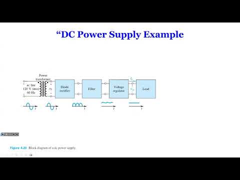
- A traditional linear supply converts outlet AC into stable low-voltage DC using a transformer, rectifier, and voltage regulator.
- The transformer steps down the voltage and provides electrical isolation from the mains supply.
- Rectification leaves ripple, which the regulator reduces; the voltage dropped across a linear regulator is dissipated as heat.
- The lecture distinguishes linear supplies, valued for precise regulation, from compact, efficient switching supplies.
- A single diode conducts during the positive half-cycle and blocks the negative half-cycle, producing pulses rather than steady DC.
- With the constant-voltage diode model, the conducting diode reduces the output by about 0.7 V.
- Half-wave rectification discards half of each AC cycle and gives the load power only during the conducting half-cycle.
- A center-tapped transformer and two diodes route both AC half-cycles through the load in the same direction.
- One diode conducts on the positive half-cycle and the other on the negative half-cycle, with a single diode drop in each path.
- The output is full-wave rectified, but only one half of the transformer secondary supplies power at a time.
- A four-diode bridge directs current through the load in the same direction for both polarities of the transformer secondary.
- Two diodes conduct in each half-cycle, so the constant-drop model gives an approximately 1.4 V total diode loss.
- Unlike the center-tapped design, the bridge uses the full transformer secondary on both half-cycles and is presented as the common practical rectifier.
- With no load connected, the filter capacitor charges toward the input peak and holds its voltage when the rectifier diode turns off.
- When a resistive load is added, the capacitor supplies load current between rectified peaks, causing its voltage to fall.
- The diode conducts when the rectified input exceeds the capacitor output; when the input falls below the output, the diode blocks and the capacitor-load path behaves as an RC discharge circuit.
- The approximate ripple relation follows from capacitor current: ΔV ≈ IₒTₛ/C, or C ≈ IₒTₛ/ΔV.
- For half-wave rectification, the discharge interval Tₛ is approximately one input period; the lecture uses this approximation despite the actual interval being slightly shorter.
- Full-wave rectification recharges the capacitor twice as often, making the interval between peaks about half as long and reducing the capacitance required for the same load current and ripple.
- The estimate assumes nearly constant load current and is intended as a practical approximation, with simulation or a differential-equation analysis available for greater precision.
- The superdiode combines an op-amp, a diode in its feedback path, and a load resistor to act as an approximately ideal diode circuit.
- For positive input, negative feedback drives the output to track the input, while the op-amp output itself rises about 0.7 V above the load-side output to overcome the diode drop.
- For negative input, the diode blocks and the load output is approximately zero.
- The circuit depends on negative feedback and an op-amp power supply, so it is more useful for signal processing than high-power rectification.
- A diode-capacitor DC restorer conducts on the negative input excursion and charges the capacitor toward the negative peak.
- When the input swings positive, the diode blocks and the stored capacitor voltage adds to the input, shifting the waveform upward.
- For an ideal diode, the shift is set by the stored peak voltage; a constant-drop model adjusts the clamp level by about 0.7 V.
- Adding a DC source VCC to the diode-capacitor restorer sets the clamp level to VCC rather than ground.
- When the input is below VCC, the diode conducts and holds the output near VCC in the ideal-diode analysis.
- When the input rises above VCC, the diode turns off and the output follows the input plus the capacitor's stored VCC offset.
- Reversing the diode orientation changes the waveform shift from upward to downward.
- The voltage doubler uses two diodes and two capacitors, analyzed by separating positive and negative input half-cycles.
- During one half-cycle, a diode charges the first capacitor to approximately the input peak voltage.
- On the opposite half-cycle, the input and stored capacitor voltage add, producing an output magnitude of about 2Vp; the shown circuit's output is negative.
- The ideal-diode result must be adjusted for real diode drops, including approximately 0.7 V per conducting silicon diode in the constant-drop model.
- The Shockley model relates diode current to voltage as I_D ≈ I_S exp(V_D/V_T), with thermal voltage V_T about 25 mV at room temperature.
- A stated operating point, such as 1 mA at 0.7 V, can be used to determine I_S and then estimate current at another diode voltage.
- The small-signal diode resistance is r_d ≈ V_T/I_D, allowing small current changes to be analyzed with a linearized circuit.
- For ideal op-amp analysis, the input currents are zero: I₊ = I₋ = 0.
- With negative feedback, the op-amp input voltages are approximately equal: V₊ = V₋.
- These rules apply to inverting, noninverting, and differential amplifier problems; the recommended preparation is lecture slides, the textbook, and homework.
Transcript excerpt
0:11 I read it first. >> I'm feeling pretty good about that. midterms like get easier as the class goes along. They do. >> If you they say well% >> [clears throat]
1:00 >> until >> we're going to get started. Um >> yeah, some student let me know that I posted wrong video for last lecture. So I repost it today. I don't know why what happened but um the lecture video should be right now. Uh any questions before we proceed? >> Yes, >> just to confirm you said that the the notes that we bring in for the exam can be they can be printed. >> Uh they can be printed but not the previous semester's exam. But if it be like pressure. >> Yeah. >> That's impressive. >> Some student have it. I >> Okay. So, no notes, any formula, anything like that. >> Any formula, any text, anything that [laughter]
1:49 there machine >> Exactly. Yeah, it's some people with those disease they cannot but they can use the eyes. >> We're going down that path more than technology. >> Yeah, >> but somebody has to design it manufacture it. That's you guys >> one day. Yeah. Okay. So, this is the last lecture and again our exam on Tuesday at 2 p.m. regular class time but not in this room in the library. Okay, if you come here, you got the wrong place. Uh if you're not familiar with the library, you should go and check it out and look on the computer, see if you can log in with open the lockdown
2:37 browser and uh yeah, try that before you know just no surprises. Uh and also, you know, to for you to prepare the exam offers office hours on Friday. So try to use that take advantage and on Tuesday we
This is the start of the transcript. Save this video free for the whole transcript, searchable and time-coded.
In this course
Related notes
Summary, takeaways, and chapters were generated by AI from the video's transcript and may contain errors. The video belongs to its creator, Wireless Power Transfer.