EE 330 Lecture 2026 10 15 Ch6 BJT#1
Overview
Chapter 6 introduces NPN and PNP bipolar junction transistors (BJTs), explaining their emitter, base, and collector structure, the approximate 0.7 V base-emitter drop, and the current relationships IC = βIB and IE = IC + IB in active operation. The lecture distinguishes BJT active and saturation regions, contrasts their naming and control behavior with MOSFETs, and works through biasing examples using β values, resistor calculations, and checks such as VCE > 0.3 V for active operation.
Key takeaways
- For a BJT in active operation, use IC = βIB and IE = IC + IB; with β = 100, α = IC/IE is approximately 0.99.
- A silicon BJT generally needs VBE near 0.7 V to conduct, and its exponential current relation uses VT ≈ 25 mV at 25°C.
- Check the operating region after solving: VCE above roughly 0.3 V supports active operation, while a transistor driven into saturation is often modeled with VCE ≈ 0.2 V.
- BJT saturation and MOSFET saturation are not equivalent: BJT amplifiers use the active region, whereas MOSFET amplifiers commonly use the MOSFET saturation region.
- In saturation, do not use the transistor's nominal β to predict collector current; calculate the circuit-limited current and then determine forced beta as IC/IB.
- When a calculated active-mode collector voltage is physically impossible, such as a negative voltage in a circuit that cannot supply it, reject the assumption and solve using saturation conditions.
Chapters
- The upcoming midterm covers Chapters 5 and 6, with an additional example-focused lecture planned for the exam week.
- The chapter will cover BJT structure, operation, current-voltage behavior, DC circuit analysis, breakdown, and temperature effects.
- BJTs remain useful in amplifier circuits, and IGBTs are introduced as a related technology for high-power applications.
- An NPN transistor has an N-type emitter, a P-type base, and an N-type collector, creating two PN junctions.
- Doped N-type material has many electrons, while P-type material has many holes; their junctions form depletion regions.
- The emitter supplies electrons, the thin base allows many to pass through, and the collector gathers electrons that cross the base.
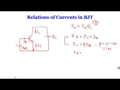
- In active operation, collector current follows the diode-like relation IC = IS e^(VBE/VT), where VT is about 25 mV at 25°C.
- Kirchhoff's current law gives IE = IC + IB, and current gain is defined as β = IC/IB.
- Typical β values are about 50 to 200, with 100 used as a common example; α = β/(β + 1), so β = 100 gives α ≈ 0.99.
- A BJT requires base current, with IE equal to the sum of collector and base currents; a MOSFET ideally draws negligible gate current.
- The lecture characterizes the BJT as current-controlled and the MOSFET as voltage-controlled.
- PNP transistors reverse the NPN layer arrangement and terminal orientation, while retaining corresponding current relationships.
- For β = 100 and IB = 10 μA, assume active operation and calculate IC = 1 mA.
- With a 5 V supply and a 3 kΩ collector resistor, VC = 5 V − (1 mA)(3 kΩ) = 2 V; the example checks VCE against the 0.3 V active-region guideline.
- Using IS = 10^-15 A and VT = 25 mV, the diode equation gives VBE ≈ 0.69 V.
- Replacing the 10 μA source with a resistor from 5 V requires RB = (5 − 0.69 V)/(10 μA) ≈ 431 kΩ.
- A practical NPN structure is formed by creating and doping regions in silicon, rather than simply joining three separate pieces of material.
- The corresponding PNP arrangement uses P-type outer regions around an N-type base.
- The middle semiconductor region is the base, with the two outer regions serving as emitter and collector.
- In active operation, IC is approximately βIB when VCE is above about 0.3 V.
- When VCE falls below roughly 0.3 V, IC no longer increases proportionally with IB, indicating saturation.
- The lecture uses about 0.2 V as a practical VCE value for a transistor driven well into saturation.
- The BJT output curve has a low-VCE saturation region and a higher-VCE active region where collector current is relatively constant.
- For amplifier operation, the lecture identifies the BJT active region as the desired region.
- MOSFET saturation is commonly used for amplification, unlike BJT saturation, so the same region name describes different operating behavior.
- For PNP devices, the lecture reverses voltage references, using VEB and VEC in place of NPN references VBE and VCE.
- In saturation, collector current is no longer set by the transistor's active-region β; the circuit establishes a smaller forced beta, βforced = IC/IB.
- The intrinsic β is treated as a transistor property, while forced beta depends on the external circuit and operating point.
- A conducting silicon BJT typically has VBE near 0.7 V, an approximate turn-on condition rather than a MOSFET-style threshold voltage.
- The exact VBE varies with current, but the lecture gives representative values around 0.69 to 0.72 V.
- At 25°C, use VT ≈ 25 mV when applying the exponential collector-current equation.
- The design target specifies a 15 V supply, a 5 V collector voltage, and IC = 2 mA; directly applying Ohm's law gives RC = (15 − 5 V)/(2 mA) = 5 kΩ.
- With β = 100, active operation gives IB = IC/β = 20 μA and IE = IC + IB ≈ 2.02 mA.
- To find RE, first determine the base-emitter voltage from a reference condition of 1 mA at VBE = 0.7 V, then use the exponential current equation to find VBE at 2 mA.
- With the base grounded, the example uses VE = −VBE and obtains VBE ≈ 0.717 V at the 2 mA operating point.
- The emitter resistor calculation gives RE ≈ 7.07 kΩ.
- The final check is VCE > 0.3 V; if a calculated operating point violates that condition, the active-mode solution must be redone using saturation assumptions.
- A second circuit specifies VE = −0.7 V, a −10 V emitter-side supply, a 10 kΩ emitter resistor, and β = 50.
- The emitter current is approximately IE = (−0.7 − (−10 V))/10 kΩ = 0.93 mA.
- Assuming active operation gives IC ≈ [50/51]IE ≈ 0.91 mA and IB ≈ IC/50 ≈ 0.02 mA.
- The calculated collector voltage yields VCE ≈ 6.15 V, comfortably above 0.3 V, confirming the active-region assumption.
- Increasing the collector resistor from 5 kΩ to 40 kΩ is intended to lower VC and push the transistor out of active operation.
- An active-mode calculation produces an impossible negative collector voltage, showing that the assumption IC = βIB cannot hold.
- Using VCE ≈ 0.2 V and VE = −0.7 V gives VC ≈ −0.5 V and IC ≈ [10 − (−0.5 V)]/40 kΩ ≈ 0.26 mA.
- The resulting forced beta is about 13, much less than the transistor's active-region β of 50.
- For the PNP example, VB = 1 V and VE = 1.7 V establish VEB = 0.7 V, so the emitter-base junction is forward biased.
- Calculate IE from the emitter resistor, then obtain IB from the base resistor and IC = IE − IB; use IC/IB to find beta.
- Find VC from the collector supply and resistor, then check VEC > 0.3 V to verify active operation; if not, use a saturation model instead.
- The lecture concludes that the worked PNP circuit is in active mode and continues the BJT chapter in the next class.
Transcript excerpt
1:43 Okay, guys. We're going to get started. So, today we're studying a new chapter in the book. Uh chapter six. So, basically I have two more chapters. This is one last second for the last and I'll be examined exactly 2 weeks. Uh we'll be testing chapter 5 and 6 only. You don't have to go back to read chapter 2 and 4. I'm sure. Um but of course, you know, if you have a need to pick up some basic concept, you're welcome to do so. Um so today we're going to cover uh BJTs. We're going to spend uh three lectures on BJT. So we spent four MOSFET. Uh and then on the day uh during the week of the exam on the Tuesday, we're going to
2:31 uh Basically, we cover a lot of examples in lecture already, but we're going to cover some additional uh examples in that lecture. So uh prepare you guys for the for the second midterm. So uh let's really get started. Um BJT is really it's another device that we use for uh small signal amplifier applications. Um as I explained a little bit earlier, uh BJT is the oldest device in terms of amplifiers. And it's been using since probably I don't know, 1930s, 1940s, and uh until the 1960s. And they replaced basically uh the vacuum tubes um that are solid
3:18 state. Until 1970s, uh MOSFET became to more and more popular. So uh but today I think it's a good idea to really look at how uh BJTs work. I I occasionally Well, I I wouldn't say occasionally, but in many applications, um we still use BJTs uh just because it's a it's still a very reliable device. And also uh when you guys get to uh 415, uh in the power electronics, you will
This is the start of the transcript. Save this video free for the whole transcript, searchable and time-coded.
In this course
Related notes
Summary, takeaways, and chapters were generated by AI from the video's transcript and may contain errors. The video belongs to its creator, Wireless Power Transfer.