EE 330 Lecture 2026 10 20 Ch6 BJT#2
Overview
The EE 330 lecture develops practical BJT analysis from the exponential base-emitter current relationship through Early effect, small-signal configurations, and cutoff, active, and saturation operation. Worked circuits show how to test an assumed operating region, calculate currents and node voltages, and recognize forced beta collapse in saturation, including examples with 10 V supplies, 0.2 to 0.3 V saturation voltages, and both NPN and PNP transistors.
Key takeaways
- At fixed VCE, BJT collector current follows the diode-like law IC = IS exp(VBE/VT), with VT near 25 mV at 25°C.
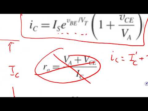
- The Early effect models the increase in IC with VCE using IC ≈ IC′(1 + VCE/VA) and an output resistance ro = VA/IC′.
- A reliable operating-region test is to assume active mode, solve the circuit, and check VCE; a negative or otherwise impossible VCE means the active-mode assumption failed.
- In saturation, VCE is approximately 0.2 V in the simplified model, and collector current is set by the external circuit rather than the active-mode β relationship.
- Forced beta can collapse sharply in saturation: the worked NPN example with ±10 V rails gives IC ≈ 5.25 mA, IB ≈ 4.05 mA, and βF ≈ 1.3.
- A BJT amplifier requires DC bias before an AC signal is applied; tying both the base and emitter of an NPN transistor to ground leaves VBE at zero and the transistor cut off.
Chapters
- With VCE held fixed, IC rises exponentially with VBE, following IC = IS exp(VBE/VT).
- At 25°C, VT is approximately 25 mV; appreciable current begins near VBE = 0.5 V and rises steeply around 0.7 V.
- The IC-versus-VBE curve and the more commonly used IC-versus-VCE output curves describe different ways of observing BJT behavior.
- As a PN junction warms, it conducts more current at a fixed voltage; for a fixed current, the required junction voltage is lower at higher temperature.
- At a fixed VBE, BJT output curves slope upward with increasing VCE rather than remaining perfectly flat.
- Extrapolating active-region curves gives the Early-voltage intercept; the model is IC ≈ IC′(1 + VCE/VA), with output resistance ro = VA/IC′.
- The Early-effect model adds a resistance ro in parallel with the collector-current source, producing an added current term VCE/ro.
- A common-emitter stage shares the emitter as the input and output signal reference; a common-collector stage has the collector at AC ground.
- A common-base stage uses the base as the shared signal reference, with input at the emitter and output at the collector.
- Common-emitter characteristics plot IC against VCE for different base currents IB; in the active region, IC is approximately βIB.
- The boundary separates active operation from saturation, where the active-region beta relationship no longer predicts collector current.
- A simple saturated-BJT model uses VCE(sat) near 0.2 V; the lecture treats about 0.3 V as the edge of saturation in an example.
- For a circuit with VCC = 10 V, RC = 1 kΩ, RB = 10 kΩ, and β = 50, setting VCE = 5 V gives IC = 5 mA, IB = 0.1 mA, and VBB = 1.7 V.
- At the stated saturation edge, VCE = 0.3 V gives IC = 9.7 mA and IB = 0.194 mA, so VBB is approximately 2.64 V.
- For deep saturation at VCE = 0.2 V and forced beta βF = 10, IC = 9.8 mA and IB = 0.98 mA; with RB = 10 kΩ and VBE = 0.7 V, the corresponding VBB is approximately 10.5 V.
- Redrawing the transistor as a simplified equivalent circuit can separate the base loop from the collector loop.
- In saturation, the approximate VBE = 0.7 V and VCE = 0.2 V drops make the two loop equations easier to visualize.
- The collector loop determines IC from the supply and RC, while the base loop relates VBB, RB, IB, and VBE.
- The analysis begins by assuming active mode, using the given β = 100 and the usual VBE ≈ 0.7 V when no other value is specified.
- The procedure finds VE from the base voltage, then IE from RE, converts IE to IC and IB, and finds VC from the collector resistor.
- The final check is VCE = VC − VE; a sufficiently positive VCE supports the active-mode assumption, while an inconsistent result requires recalculation in saturation.
- With VBB = 6 V, β = 50, and RE = 3.3 kΩ, an active-mode assumption gives VE ≈ 5.3 V and IE ≈ 1.6 mA.
- The predicted collector voltage is only about 2.5 V, making VCE negative; that physically inconsistent result rules out active operation.
- Using VCE(sat) = 0.2 V instead gives VC ≈ 5.5 V and IC ≈ 0.96 mA through RC = 4.7 kΩ; IB is about 0.64 mA, so forced beta is only about 1.5.
- When an NPN transistor has both base and emitter at ground, VBE = 0, the device is off, and collector current is zero.
- With no collector current, there is no drop across RC, so the collector remains at VCC; the circuit cannot amplify an input signal in this state.
- An amplifier needs a DC bias that forward-biases the base-emitter junction, while the AC input is superimposed on that operating point.
- For the PNP example, the analysis labels VE, VC, and VB explicitly and uses current directions appropriate to a PNP transistor.
- With a 5 V emitter-side supply, VBE magnitude near 0.7 V, and RE = 2 kΩ, the emitter current is about 4.65 mA.
- Assuming β is effectively infinite makes IB approximately zero and IC approximately IE; the collector resistor and negative supply then determine VC, followed by an active-region check.
- The PNP calculation uses VC ≈ −5.35 V and checks the collector-emitter voltage against the active-region condition.
- For the complementary NPN setup, grounding the base places the emitter near −0.7 V, giving IE ≈ 9.3 mA through a 1 kΩ emitter resistor.
- An active-mode calculation predicts an impossible collector-emitter voltage, so the NPN circuit must be analyzed in saturation instead.
- With VCE(sat) ≈ 0.2 V and VE ≈ −0.7 V, the collector is about −0.5 V; a 2 kΩ collector resistor connected to +10 V then carries IC ≈ 5.25 mA.
- The emitter current remains about 9.3 mA, so IB = IE − IC is about 4.05 mA and forced beta is only about 1.3, despite the initial infinite-beta assumption.
- The NPN and PNP circuits are not automatically symmetric: swapping transistor polarity also changes which resistor belongs at the emitter and collector.
- The next lecture is set to apply Thevenin and Norton equivalents to more complicated BJT bias networks.
- Planned topics include multistage circuits and additional examples intended to complete the chapter's circuit-analysis methods.
Transcript excerpt
0:00 And today we're going to go through a few more examples and to illustrate how uh we can solve BJT problems from different angle. Uh before we do that, I want to look at the current voltage relationship between what happens to VBE and IC. You know, and I will draw another diagram on the side for you to compare. So, when you have a BJT when we apply VBE at the base, we we will give a fixed let's say VCE. So, let me draw the circuit diagram. So, it will look like this. This is going to be So, let's say we have this BJT
1:00 is it doesn't matter whether it's NPN or PNP principle is going to be the same. Then we inject um we apply VCE with a constant voltage on there and then we inject uh or we apply a voltage between base and emitter and we vary VBE see what happens. And we measure the current IC uh across the BJT. So, the current IC is like this. So, what happens with this IC is that when VBE is very small there's no current. So, when VBE increases around 0.5 you will start to see some current flowing. And then when VBE is close to 0.7 the current starts to shoot
1:48 up like vertically. See, you probably can recall what is this this relation? Like where have we have we we seen this before? It's a diode. So, basically what we are saying is IC is equal to IS times E to the power VBE over VT. So, that's what we haven't seen over here. We have VT equal to 25 mV at 25 C. This is exactly what happens. It's It's like a BJT. So, I mean a BJT is exactly like a diode.
This is the start of the transcript. Save this video free for the whole transcript, searchable and time-coded.
In this course
Related notes
Summary, takeaways, and chapters were generated by AI from the video's transcript and may contain errors. The video belongs to its creator, Wireless Power Transfer.