ECircuits-Lec10-2026
Overview
The lecture develops a practical method for analyzing op-amp circuits with finite gain, input resistance, and output resistance. It distinguishes ideal closed-loop gain from nonideal behavior using the loop-gain relation A = A∞/(1 + 1/T), then applies ideal-op-amp analysis and feedback-factor calculations to voltage, current, transconductance, and transimpedance circuits.
Key takeaways
- For a nonideal op-amp, calculate the ideal closed-loop gain A∞ and feedback factor β separately, then use A = A∞/(1 + 1/(Aβ)) to estimate the actual gain.
- Ideal voltage amplifiers require infinite input resistance and zero output resistance; ideal current-input amplifiers require zero input resistance so source current is not lost.
- An ideal transconductance amplifier has voltage input, current output, gain in siemens, and ideally infinite input and output resistance.
- An ideal transimpedance amplifier has current input, voltage output, gain in ohms, and ideally zero input and output resistance.
- The worked nonideal inverting amplifier uses A = 400 and β ≈ 0.178, giving loop gain 71 and a closed-loop gain magnitude near 1.97 instead of the ideal 2.
- Zero output resistance means a voltage source can maintain its voltage under load; it does not mean the source voltage itself is zero.
Chapters
- Prelab work is required before attending the lab, and Homework 2 is due that night.
- The ideal closed-loop gain is A∞; finite open-loop gain is analyzed with A = A∞/(1 + 1/T).
- Loop gain is T = Aβ, where A is the op-amp's finite gain and β is the feedback-path factor.
- The key nonideal calculation is finding what fraction of the output is fed back through the circuit resistors.
- Model the nonideal op-amp with input resistance RA, a dependent source A·VD, and output resistance RO.
- Trace the output signal through the resistor network toward the op-amp input to calculate β.
- Combine resistor groups into equivalent values such as RX and RY, then multiply successive voltage-divider ratios.
- At each divider, use the resistance across which the desired feedback voltage appears, not simply the resistor nearest the output.
- An ideal op-amp input draws no current, so an input connected directly to that terminal has infinite input resistance.
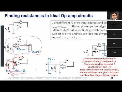
- For a negative-feedback inverting amplifier with a virtual-ground input node, a test voltage sees R1 when there is a return path through the feedback network.
- A voltage amplifier ideally has infinite input resistance and zero output resistance, preventing source-voltage loss and load-dependent output drop.
- A voltage follower has unity ideal gain, infinite input resistance, and zero output resistance.
- A transconductance amplifier converts input voltage to output current, so its gain IO/VS has conductance units.
- For the ideal circuit, the virtual-ground relation gives IO = VS/R1 and A∞ = 1/R1.
- Its ideal input resistance is infinite, while its output resistance is infinite so the output behaves like an ideal current source.
- To test output resistance, zero the independent input source and apply a test source; with no output test current, Rout is infinite.
- An inverting current-to-voltage circuit has ideal gain VO/Iin = −R2, a transimpedance measured in ohms.
- A current-input amplifier ideally has zero input resistance so nearly all input current enters the circuit instead of being diverted by source nonideality.
- The virtual-ground input node makes the voltage across the input current source zero, so the circuit input resistance is zero even though the op-amp itself has infinite input resistance.
- Because the output is voltage, the transimpedance amplifier ideally also has zero output resistance.
- An ideal current buffer routes all input current to its output, giving current gain IO/Iin = 1.
- The current buffer has zero input resistance and infinite output resistance, matching the ideal requirements for a current input and current output.
- A current amplifier can be formed by changing the resistor network; the lecture gives an ideal gain form of 1 + R2/R1.
- Op-amp networks can also implement integrators and differentiators by introducing capacitors.
- For ideal analysis, R3 carries no current and does not affect the gain; the circuit reduces to an inverting amplifier with gain magnitude R2/R1 = 20 kΩ/10 kΩ = 2.
- The nonideal example uses op-amp gain A = 400, input resistance RA = 80 kΩ, and output resistance RO = 1 kΩ, with R3 = 30 kΩ and R4 = 4 kΩ.
- The feedback network is reduced to RX ≈ 9.17 kΩ and RY ≈ 3.52 kΩ, then divider ratios give β ≈ 0.178.
- The loop gain is T ≈ 400 × 0.178 = 71, so the closed-loop gain magnitude is about 2/(1 + 1/71), or 1.97.
- With input and output both defined as currents, the circuit is a current amplifier and its gain is IO/Iin.
- Ideal op-amp input currents are zero, and the virtual-ground condition makes the current through R1 zero, directing the input current through R2.
- The voltage across R4 is Iin·R2, so its current is Iin·R2/R4; KCL yields A∞ = −(1 + R2/R4).
- For the example resistor ratio R2/R4 = 5, the ideal current gain is −6.
- A student question prompts a distinction between an ideal voltage source's zero output resistance and its actual output voltage.
- Zero source resistance does not mean zero voltage; the op-amp's internal dependent voltage source can maintain a nonzero output.
- In the current-amplifier example, the output-node voltage is Iin·R2, which drives current Iin·R2/R4 through R4.
- The negative sign in the gain follows from the defined IO direction being opposite to the resulting output-current direction.
- The current amplifier's input resistance is zero because the input node is held at virtual ground; the op-amp's own input resistance remains infinite.
- Its output resistance is infinite: zero the independent input current source, then an output test source produces no current in the open output path.
- The same resistor network as the earlier voltage-amplifier example gives β ≈ 0.178 and T ≈ 71; changing the output definition changes the numerator, not these feedback terms.
- Homework 2 asks for A∞, Rin, and Rout using an ideal op-amp, followed by β and nonideal closed-loop gain for the nonideal case.
Transcript excerpt
0:00 recording. >> Okay. So, first off, uh we have our lab starting today. Again, please make sure that you have all your prelab sections done before you attend the lab. Um the homework two is also due tonight. Uh so, please make sure you complete homework two and submit. Uh we'll be discussing a few more example problems in today's lecture that can help you in solving homework two related problems. Uh but these are the same problems that have been uploaded earlier in Canvas. All right. So the basic goal in homework two what we were what we have been trying to do is u finding out what is the gain of the opamp system
0:49 if the opamp is not ideal. uh you already found out or in 31 or in your previous classes you already know how to find out the gain of the system. If the opamp is ideal and if the opamp is ideal we are calling the gain of the system as a infinity which I think we already discussed in some of our previous lectures that a infinity is the gain of the overall system from the input to the output. If that opamp is ideal and if its gain is infinite and in that case the if if the opamp becomes non ideal the way to find out the gain of the whole system is how we represented it and we proved it in the previous lectures that the overall gain is going to be a infinity divided by 1 + 1 / t. Why we represent it in this form
1:37 and again we've proved this from feedback theorem that this is nothing but a divided by 1 + a beta. But why do we represent this in this form? Because your numerator becomes something that is
This is the start of the transcript. Save this video free for the whole transcript, searchable and time-coded.
In this course
Related notes
Summary, takeaways, and chapters were generated by AI from the video's transcript and may contain errors. The video belongs to its creator, WISE Lab - UF ECE.