ECircuits-Lec9-2026
 Watch on YouTube →
Overview
The lecture reviews how to analyze op-amp feedback systems using the ideal-system gain A∞, loop gain T = Aβ, and the closed-loop relation Acl = A∞/(1 + 1/T). It applies test sources and ideal-op-amp assumptions to input and output impedance, develops a transconductance-amplifier example, and calculates a finite-gain case with A = 400, β = 0.178, T ≈ 71, and closed-loop gain ≈ 1.97. Several output-resistance examples remain uncertain during class, and their derivations are deferred for review.
Key takeaways
- For a negative-feedback system, loop gain is T = Aβ, and finite-gain closed-loop gain can be written as A∞/(1 + 1/T); an ideal op amp makes T infinite and removes the finite-loop-gain correction.
- A∞ describes the whole circuit's ideal closed-loop gain, not the op amp's open-loop gain; for a non-inverting amplifier it is 1 + R2/R1.
- Circuit-level input and output impedance must be measured at the specified port using a test source after independent sources are deactivated; an ideal op amp's own infinite input impedance and zero output impedance do not determine the complete circuit's port impedance.
- Virtual ground can make a circuit's input impedance finite or even zero despite the op amp's infinite input impedance, depending on the resistive paths and the terminals used for the measurement.
- A voltage-to-current amplifier benefits from infinite input resistance and infinite output resistance; the example produces Iout/Vs = 1/R1 and ideally sends output current through the load.
- In the finite-gain example, A = 400 and β = 0.178 yield T ≈ 71 and reduce an ideal gain magnitude of 2 to about 1.97; some separate output-resistance derivations are explicitly left unresolved.
Chapters
- Lab sessions begin Monday, and each student must finish the prelab before attending the in-lab session.
- Prelab submissions are due 15 minutes before the student's scheduled lab period, whether it is Tuesday, Thursday, or another section.
- Homework 2 is due September 14, and the lecture promises additional worked examples to support it.
- A∞ means the closed-loop gain of the entire circuit when the op amp has infinite gain, not the op amp's open-loop gain.
- For a non-inverting amplifier, the ideal-system gain is A∞ = 1 + R2/R1.
- The forward-path gain A multiplied by feedback factor β gives loop gain T = Aβ; opening the loop and applying a test voltage illustrates the cascaded gain.
- The closed-loop gain is A/(1 + Aβ), equivalently A∞/(1 + 1/T); with an ideal op amp, T is infinite and the gain reduces to A∞.
- A terminal is a circuit node that can be used in Kirchhoff's Current Law analysis.
- A port is a pair of terminals where current entering one terminal equals current leaving the other.
- A terminated port has a connected circuit or load; an unterminated port is open-circuited.
- To find an equivalent impedance, deactivate independent sources, apply a test voltage or current at the port, and calculate Z = Vtest/Itest.
- Capacitor impedance is 1/(sC), while inductor impedance is sL; for resistor-only circuits, impedance is resistance.
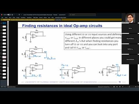
- The quantity requested is the impedance of the complete circuit at its port, not the ideal op amp's known infinite input or zero output impedance.
- Looking into an ideal op amp's non-inverting input gives infinite circuit input impedance when no other path draws current.
- In a resistor-fed inverting configuration, the virtual-ground node makes the input impedance seen at the source equal to R1, despite the op amp's infinite input impedance.
- A second configuration is analyzed by applying a test source across two terminals; the discussion distinguishes that measurement from output impedance measured relative to ground.
- The class identifies uncertainty in one output-impedance derivation and postpones resolving the apparent finite-versus-infinite result.
- When finding the impedance looking into a black box, remove the external load RL and calculate the equivalent impedance of the box alone.
- The load's effect is considered after finding the box impedance, by reconnecting RL to the equivalent circuit.
- A test source placed between two specified terminals measures impedance across that pair, which can differ from measuring a node relative to ground.
- The lecture uses virtual ground and Ohm's law to explain why some terminal pairs appear shorted, while flagging another output-resistance case for later verification.
- The ideal non-inverting amplifier has gain 1 + R2/R1, infinite input resistance, and zero output resistance; the voltage follower has gain 1 with the same ideal impedance properties.
- A current-output op-amp circuit is analyzed using Iout/Vs; virtual short behavior gives Iout = Vs/R1 and transconductance 1/R1.
- The current-output circuit has infinite input resistance and, in the ideal analysis, infinite output resistance, directing current into the load rather than an internal shunt path.
- The discussion emphasizes that circuit impedances can differ from the ideal op amp's own impedances, just as circuit gain differs from the op amp's open-loop gain.
- For the example inverting topology, ideal op-amp analysis gives gain −R2/R1; R3 has no effect when the non-inverting input current is zero, and the ideal output can drive the R4 load.
- The example uses a finite op-amp gain A = 400 and obtains feedback factor β = 0.178 from a resistor network containing 4 kΩ, 20 kΩ, 10 kΩ, 80 kΩ, and 30 kΩ elements.
- The resulting loop gain is T = Aβ ≈ 71, so a nominal ideal-system gain magnitude of 2 becomes approximately 2/(1 + 1/71) = 1.97.
- The worked case reports nonideal input resistance of 80 kΩ and output resistance of 1 kΩ, illustrating that finite op-amp gain can degrade circuit performance.
- A test voltage Vx is applied at the output port to determine output resistance from the resulting test current.
- The derivation raises a question about how current can flow through a 20 kΩ resistor when nodes are described as being at zero volts.
- The instructor does not finalize the result, noting that the circuit may contain a path to ground and promising to revisit the special case in the next lecture.
- Students are directed to the Lecture 9 notes for additional loop-gain examples relevant to Homework 2.
Transcript excerpt
0:01 All right, so let's get started. First off, uh the labs are going to start on Monday. Again, just a reminder, please make sure you attend your respective lab session starting this Monday and make sure that you have your prelab s section done before you are actually attending the lab. The lab will only constitute the inlab section of each of the lab assignments. But make sure that you are done with your prelab section before the lab starts. Also, homework two will be due on September 14 that is this Monday. Uh we already discussed a little bit about how to solve homework two like problems and we'll see more examples in today's lect >> the prelabs all the prelabs. So for example lab one there is a prelab
0:49 section there is an inlab section. So you have to make prelab means something that needs to be done before the lab. So it needs to be completed before the lab actually happens. >> Uh so if you go to your for example assignments uh let's so you'll see something like this. your upcoming assignments. Homework two is due. Lab one prelab is due. So if you just open it, you'll see that the all the all the uh directives are given. So you need to submit your prelab assignment 15 minutes before the start
1:36 of your lab period. So if you're on a Tuesday lab section, submit it before your lab period, 15 minutes before that lab session. But if you're on let's say Thursday, all you need to do is submit your prelab section 15 minutes before your lab session. So that's sufficient. Uh but do not submit it after your lab has already happened. So prelab means it needs to be submitted before the lab. Okay? And you can just upload your
This is the start of the transcript. Save this video free for the whole transcript, searchable and time-coded.
Related notes
Summary, takeaways, and chapters were generated by AI from the video's transcript and may contain errors. The video belongs to its creator, WISE Lab - UF ECE.