EAS4200 Aerospace Structures, Lecture 8, 2026 fall
Overview
Ting Dong reviews bending, transverse shear, and torsional stress equations, then applies them to a circular-section L-shaped structure loaded by a 15 lb force with 9 lb and 12 lb components. The worked example identifies critical points A through D, calculates stress components from axial load, bending, transverse shear, and torque, and begins assembling the stress tensor at point A.
Key takeaways
- Bending stress is zero on the neutral surface and grows linearly with distance from it; the extreme-fiber value is Mc/I.
- For a rectangular section, transverse-shear stress peaks at the neutral surface at 3V/(2A), while for a circular section the maximum is 4V/(3A).
- Circular-shaft torsional stress increases linearly from the center to the outer radius, which explains why hollow shafts can reduce weight without removing the most effective material.
- The 15 lb load in the L-shaped example resolves into Fx = 9 lb and Fy = 12 lb; these components generate distinct bending moments because their lever arms and bending axes differ.
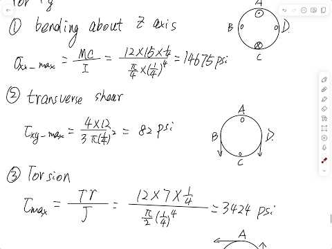
- For the example's 0.25 in-radius section, Fy produces about 14,675 psi maximum bending stress, 82 psi maximum transverse shear, and 3,424 psi torsional shear.
- A stress tensor must place shear components in the correct coordinate positions and remain symmetric, so tau_xz equals tau_zx.
Chapters
- For bending, normal stress varies linearly with distance y from the neutral surface: sigma = -My/I, with zero stress at y = 0.
- Maximum bending stress uses the farthest distance c from the neutral axis: magnitude = Mc/I.
- For a rectangular section, I = bh^3/12 about the indicated axis; for a solid circular section, I = pi r^4/4.
- Transverse shear stress is tau = VQ/(It), where V is the internal shear force, Q is first moment of area, I is moment of inertia, and t is local thickness.
- In a rectangular section, shear stress is zero at the top and bottom and reaches its maximum at the neutral surface, with tau_max = 3V/(2A).
- For a solid circular section, the maximum transverse shear is 4V/(3A), also at the neutral surface.
- For a circular shaft, torsional shear varies linearly with radius: tau = T rho/J, reaching its maximum T c/J at the outer surface.
- A solid circular section has polar moment J = pi r^4/2; a hollow section has J = pi(ro^4 - ri^4)/2.
- Removing material near the shaft center can reduce weight while retaining outer material, where torsional shear stress is greatest.
- The example asks for the stress state at points A, B, C, and D, followed by principal stresses and maximum shear stress at point A.
- The L-shaped member has 15 in and 7 in lever arms and a circular cross-section with radius 0.25 in.
- The applied 15 lb force is resolved into Fx = 9 lb and Fy = 12 lb using a 3:4:5 ratio.
- Dong emphasizes that structural problems may require identifying the critical location rather than being told where maximum stress occurs.
- At point A, axial tension and bending about the z-axis contribute normal stress; torsion contributes shear stress.
- Although Fy creates internal transverse shear, its transverse-shear stress is zero at the top and bottom points A and C.
- The 9 lb Fx component creates uniform axial stress across the circular section, calculated as sigma = Fx/A.
- Fx also creates a bending moment about the y-axis with a 7 in moment arm; point B is in maximum tension and point D in maximum compression.
- For this bending contribution, A and C lie on the neutral surface and have zero normal stress; the maximum magnitude is 5,136 psi.
- The 12 lb Fy component creates bending about the z-axis with a 15 in moment arm, producing a maximum normal-stress magnitude of 14,675 psi.
- For bending from Fy, A is in maximum tension and C in maximum compression; B and D are on the neutral surface.
- Fy also produces maximum transverse shear of about 82 psi at B and D, while A and C have zero transverse-shear stress.
- Fy acting at a 7 in offset creates a torque of 84 lb-in about the x-axis.
- Using tau = Tc/J for the 0.25 in-radius circular section gives a torsional shear magnitude of 3,424 psi.
- Torsional shear acts at all four perimeter points A through D, with its direction changing around the section according to the applied torque.
- At point A, Dong combines axial tension with bending tension from Fy in the sigma_xx entry of the 3-by-3 stress matrix.
- The torsional shear is entered as tau_xz, with the equal symmetric component tau_zx required for equilibrium.
- The lecture stops after assembling the stress state at A; principal stresses and maximum shear are identified as the next calculation task.
Transcript excerpt
0:21 How about now? I'm sorry. Um uh I forgot to turn on. Thank you for reminding me. Um so before we start I want to do a quick review of the equations we learned from Mikas materials. How to calculate normal stress c by benning. How to calculate she stress c by torsion. How to calculate shar stress caus by transverial force. Uh I'm not going to do any kind of derivation because that was content mechanic materials. If you want to know more detail um come to more saw but here is just quick review. So uh tension compression I will skip that um because that is like simple enough. I
1:10 will start from the bending. So let's assume a simple can be situation and of course um we can have different situation to generate a bending. can apply a cover at the free end or I can apply a um transverse force applied at the very end. You can also gen generate a bending moment and for this normal stress generate bending. If I put the coordinate as uh actual direction as x direction and upward as positive y direction xyz and outer plane is z direction. So in this situation for the bending Normal stress cause a bending sigma xx
2:11 negative my fi right um and for this one if we want to know how the normal stress change over the cross-section well for a specific cross-section m is a constant value right bending moment does not change on a specific cross-section let's say if I take cross-section here at the root then f times this distance becomes bending moment if I take a cross-section at this middle then f times half of l become the magnitude of bending moment on this cross-section so if we know the point
This is the start of the transcript. Save this video free for the whole transcript, searchable and time-coded.
In this course
Related notes
Summary, takeaways, and chapters were generated by AI from the video's transcript and may contain errors. The video belongs to its creator, Ting Dong.