EAS4200 Aerospace Structures, Lecture 32, 2026 Fall
Overview
Ting Dong completes a two-cell thin-walled torsion example, using equal cell rotations to determine the cell shear flows, then recovering the applied torque and torsional constant with T = 2A₁Q₁ + 2A₂Q₂ and T = GJθ. The lecture then derives the bending-induced shear-flow relation from force equilibrium and applies it to a symmetric thin-walled section, showing linear shear-flow variation along a flange and quadratic variation along a web.
Key takeaways
- In a bonded multi-cell thin-walled section, compatibility requires the same twist rate in every cell; this additional equation lets the cell shear flows be solved.
- The total torque carried by two closed cells is the sum of their Bredt contributions, T = 2A₁Q₁ + 2A₂Q₂, using signed cell shear flows.
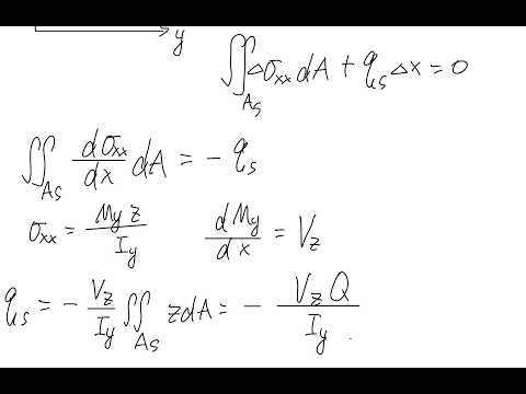
- Bending-induced shear flow arises when the bending moment varies along the beam, because that variation creates nonzero internal shear force and an axial-stress gradient.
- The relation qₛ = VQ/I uses the first moment Q of the selected cut area, but I is calculated for the entire cross-section.
- For the illustrated thin-walled geometry, shear flow grows linearly from a free edge along the flange and varies quadratically along the web because the cut-area centroid moves as the cut advances.
- Shear flow is continuous through the flange-web junction: the web begins with the flange-corner value rather than resetting to zero.
Chapters
- The example uses a two-cell thin-walled section with wall thicknesses T₁, T₂, and shared-wall thickness T₁₂.
- Dimensions are measured along wall centerlines; the explanation treats these as direct inputs rather than modeling local thickness offsets.
- Compatibility requires θ₁ = θ₂, because the two cells must rotate together without separating at their shared wall.
- After solving the two compatibility equations for cell shear flows Q₁ and Q₂, total torque follows from T = 2A₁Q₁ + 2A₂Q₂.
- The shared-wall flow uses opposite signed contributions from the two cells: Q₁ − Q₂ for cell 1 and Q₂ − Q₁ for cell 2.
- The torsional constant is found from T = GJθ, rearranged as J = T/(Gθ), with the result in units of length to the fourth power.
- Ting Dong closes the thin-walled torsion topic and introduces shear flow caused by bending, planned as a two-class subject.
- The derivation begins with a cantilever beam fixed at one end and loaded by a transverse force at the free end.
- The coordinate convention sets the beam axis as x, the vertical direction as z, and the in-plane cross-section direction as y.
- Pure bending has a constant bending moment and zero internal shear force, so it does not produce the bending-related shear flow derived here.
- A transverse load makes the bending moment vary along x, creating nonzero internal shear force and a change in bending normal stress σₓₓ.
- The section is assumed symmetric about the y-axis, and the derivation tracks shear flow along a contour coordinate s.
- A short beam element of length Δx is isolated; the change in σₓₓ across its ends is balanced by shear flow acting over Δx.
- Integrating the normal-stress change over the selected cut area and applying force equilibrium links shear flow to the bending-stress gradient.
- Using the bending stress relation and the connection between bending-moment gradient and shear force gives the thin-wall relation qₛ = VQ/I, with sign set by the chosen direction convention.
- Q is the first moment of the selected cut area about the neutral axis, calculated as the area times the z-coordinate of that area's centroid.
- The selected area changes as the cut moves along the wall, so Q and shear flow vary with contour position.
- Iᵧ is always the second moment of area of the entire cross-section, not the moment of inertia of the small cut area.
- For the upper flange, Ting Dong measures s from the free edge and uses flange thickness t, flange length B, and centroid offset H.
- The cut area grows as A = ts, while its centroid remains a distance H from the neutral axis, giving a shear-flow magnitude proportional to s.
- Shear flow starts at zero at the free edge and reaches its flange maximum at the corner where s = B.
- The vertical web does not restart at zero shear flow: its starting value equals the accumulated flow at the flange corner.
- For a distance s′ measured downward from the web's top, the added cut area is a rectangle with area ts′ and centroid determined from the web geometry.
- The centroid offset changes as s′ increases, making the web shear-flow expression quadratic rather than the flange's linear expression.
- The web distribution is symmetric about its midpoint, where s′ = H; the lecture identifies this location as the maximum-magnitude point.
- At the web's bottom, s′ = 2H, the symmetry of the section gives the same shear-flow magnitude as at the top corner.
- Near the end, a student asks whether homework problem 3's shear center is point C, but the transcript ends before Ting Dong's answer.
Transcript excerpt
0:01 For students in the back, can you hear me? Okay, so if anytime cannot hear me, just let me know. Uh so let's continue with our content in the last class. So we talked about that uh now we expand this close uh close section from single cell to uh multiple cell and of course the example I'm giving here is is two cells. You can apply to uh more. Let's see. So the example problem uh was we have a double cell structure and um the thickness they are given for each section. So basically um this one, this one, this one have same thickness T1 and this one, this one, and this one have
0:50 same thickness T2 and the shared wall had the thickness T12. Uh and of course students ask me like after class so so basically are um I drew this part like the same but and how do the centerline um align to uh in the whole top and bottom section. So basically you just imagine that uh you expand this one and this one outward uh 0.1 cm um and in this way the centerline is a straight line. Uh but of course I didn't really draw this in detail because I mean if um putting this in detail you will see oh there's a stress concentration it get get more and more complicated. Let's only focus on our uh content here. Centerline dimension is given. Don't go too crazy like
1:37 how how does this double thickness and the centerline still aligned? Um you just imagine this expanding in the in outward and this is also a centerline dimension and the dimension given here is also centerline. You can use directly. Um so we talked about that for calculating this um multi cell thin wall section, close section uh the
This is the start of the transcript. Save this video free for the whole transcript, searchable and time-coded.
In this course
Related notes
Summary, takeaways, and chapters were generated by AI from the video's transcript and may contain errors. The video belongs to its creator, Ting Dong.