EAS4200 Aerospace Structures, Lecture 9, 2026 fall
 Watch on YouTube →
Overview
Ting Dong works through an L-shaped aerospace structure to show how to identify its critical cross-section, resolve applied forces into axial, bending, transverse-shear, and torsional stresses, and assemble stress tensors at points A through D. The method emphasizes checking every nonzero component, applying tensor sign and subscript conventions consistently, then finding principal stresses and maximum shear stress from the stress tensor.
Key takeaways
- The critical cross-section is identified by the largest bending moment arm, and the critical point is then determined from the bending-stress distribution across that section.
- For the L-shaped structure, Fx contributes both axial normal stress and bending about y, while Fy contributes bending about z and transverse shear; an offset load can also produce torsion.
- A reliable stress calculation includes every nonzero contribution, even when bending stress dominates the smaller axial, transverse-shear, or torsional-shear terms.
- Stress tensor subscripts identify plane first and direction second, and shear components must be placed with their symmetric counterparts, such as τxz = τzx.
- Principal stresses come from the eigenvalues of the stress tensor, and the maximum three-dimensional shear stress is (σ1 − σ3)/2.
- The worked procedure generalizes to rectangular sections, added forces and moments, and design questions that ask for allowable load or minimum dimensions.
Chapters
- The section with the largest moment arm experiences the largest bending moment and is treated as the critical cross-section.
- At that section, bending normal stress is typically much larger than axial tension, transverse shear, or torsional shear in the worked example.
- Engineers must identify both the critical section and the critical point on it rather than expect the problem statement to specify them.
- Fx produces axial tension across the section and a bending moment about the y-axis through its lever arm.
- For bending about the y-axis, points B and D have opposite maximum normal stresses, while A and C lie on the neutral surface.
- Fy produces bending about the z-axis; in the illustrated orientation, A and C carry opposite extreme bending stresses while B and D lie on the neutral surface.
- A downward transverse force creates shear across the section, while its offset from the structure’s axis creates a torque and torsional shear.
- For this course, calculate every stress component that is not zero, even when it is smaller than bending stress.
- Zero components may be omitted, but students should not discard nonzero transverse-shear or torsional-shear terms based only on relative size.
- Determine torque using the force’s perpendicular moment arm about the rotation axis, separate from the bending moment calculation.
- In the second-order stress tensor, the first subscript identifies the plane and the second identifies the stress direction.
- At the shown cross-section, stresses on the x-plane use x as the first subscript: shear in y is τxy and shear in z is τxz.
- Normal stress acts perpendicular to a cross-section; shear stress acts parallel to it, so Fy does not create axial normal stress on the x-section.
- Bending produces normal stress along the member’s axial direction, regardless of whether the bending moment acts about the y- or z-axis.
- At point A, combine the applicable axial and bending contributions in σxx, then place shear components in their matching off-diagonal tensor positions.
- At point B, combine its axial and bending normal stresses with the applicable transverse shear component τxy.
- The tensor is symmetric: τxy equals τyx, τxz equals τzx, and τyz equals τzy.
- Use the stress direction and the plane orientation to set signs, rather than copying a shear magnitude without checking its direction.
- At point C, add axial tension and the applicable compressive bending contribution in σxx, then place torsional shear in the xz and zx positions.
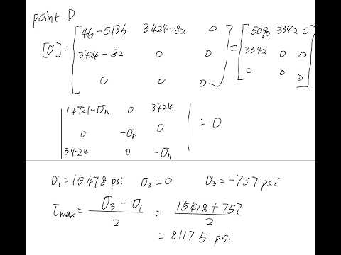
- At point D, combine axial tension with its bending normal stress and include the relevant transverse-shear and torsional-shear terms.
- For shear on the positive x-plane, a component directed along negative y or negative z receives a negative sign; the opposite direction receives a positive sign.
- The stresses at A, B, C, and D differ because bending varies by location and different points carry different shear components.
- Find principal stresses by forming the characteristic equation det(σ − λI) = 0 for the point’s stress tensor.
- The principal stresses are the eigenvalues of the stress tensor; Ting Dong demonstrates the procedure for point A and applies the same method to B, C, or D.
- The three-dimensional maximum shear stress is half the difference between the largest and smallest principal stresses: τmax = (σ1 − σ3)/2.
- On Mohr’s-circle plots, this maximum corresponds to the radius of the largest circle.
- The same workflow applies if the example changes to a rectangular cross-section or adds forces in x, y, or z, applied moments, or torque.
- An allowable-stress version of the problem can be used to solve for a minimum structural dimension or maximum permitted applied force.
- The lecture closes with questions about the upcoming Monday quiz and notes that the problem statement and questions will be provided.
Transcript excerpt
0:00 So in the last class we talked about this example problem. So this is just one of the typical example problem and I'm only going to do one example. I'm expecting you guys can do all kinds of relation based on this example problem. Um so basically we have the L-shaped structure and ask about the AB CD um at a critical cross-section and of course for this critical cross-section um as engineer you need to figure by yourself this critical cross-section is here because this is the place with the biggest moment arm and when I say it has biggest moment arm it mean that it has the maximum moment and when it has maximum moment it has maximum normal stress caused by the bending moment, right? And also you guys probably practice enough in the mechanic
0:47 materials when for the same force it can cause uh torque. So she stress generated by torque. It can also cause shared by trioral force. And this same force can also cause by bending. Uh chaos cause bending and I have the normal stress generated by bending and uh based on what all the practice you have done before you probably already realize that for the same force cause all those different stresses always normal stress gen bending is much larger than the rest. So uh I can show you for this one for example we have you can just check the number we calculate here. This is normal stress caused by tension. Normal stress caused by tension. This is the normal stress caused by bending. You see a significant difference.
1:34 This is the normal stress caused by bending again. This is the shear stress caused by transverse sheer force. This is the shear stress caused by torsion. So by simply check this example
This is the start of the transcript. Save this video free for the whole transcript, searchable and time-coded.
Related notes
Summary, takeaways, and chapters were generated by AI from the video's transcript and may contain errors. The video belongs to its creator, Ting Dong.