EAS4200 Aerospace Structures, Lecture 30, 2026 Fall
Overview
Ting Dong derives the torsional behavior of thin-walled closed sections, emphasizing that the closed-section equations must not be confused with open-section formulas. Using torque equilibrium and strain energy, the lecture obtains the closed-cell torsional constant, compares closed and open circular shafts, and applies the shear-flow method to a variable-thickness section with a 200 MPa allowable shear stress.
Key takeaways
- For a thin-walled single-cell closed section under torque, T = 2Aq, where A is the area enclosed by the wall median line and q is the contour shear flow.
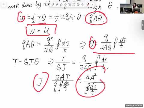
- The closed-section torsional constant is J = 4A² / ∮(ds/t), so both the median-line enclosed area and the distribution of wall thickness govern torsional stiffness.
- The shear-flow relation q = τt applies to open and closed walls, but the closed-cell torque and torsional-constant equations must not be applied indiscriminately to open sections.
- For a single-cell closed section under torque, shear flow is constant around the contour; because τ = q/t, the thinnest wall location controls the maximum shear stress.
- Closing a thin-walled section constrains relative edge motion and reduces warping, explaining why a closed tube can resist torsion much more effectively than a similar tube with a slit.
- In the 2 m by 1.2 m design example, the allowable torque is found by calculating median-line area, using the 5 mm minimum thickness, and enforcing τmax ≤ 200 MPa.
Chapters
- Ting Dong stresses that the derivation applies to closed sections only, a distinction students should preserve when selecting equations for tests and exams.
- The thin-wall assumption treats wall thickness as much smaller than the full contour dimensions, so transverse shear stress through the wall can be neglected.
- Shear flow is defined as shear stress times local thickness, q = τt, and this relation applies to both open and closed sections.
- For a small contour segment Δs, the shear-flow force is qΔs and its moment contribution follows from the segment’s perpendicular distance to the twist center.
- Integrating around the entire closed contour gives the torque relation T = 2Aq.
- A is the area enclosed by the wall centerline, also called the median line or shear-flow path, not the material cross-sectional area.
- Local shear stress follows from τ = q/t, so varying wall thickness must be evaluated at the specific contour location.
- With shear modulus G, the shear strain is γ = τ/G = q/(Gt).
- Because the thin-wall torsion model retains only the contour-direction shear components, strain energy per unit length is obtained by integrating q²/(2Gt) along the wall.
- The lecture equates strain energy to the work of the applied torque, using half the torque times the twist for a linearly elastic response.
- Combining that energy balance with T = 2Aq yields the single-cell thin-wall result J = 4A² / ∮(ds/t).
- The twist per unit length is related to torque by θ′ = T/(GJ), making GJ the section’s torsional rigidity.
- Ting Dong clarifies that A is not the solid cross-sectional area; it is calculated from the centerline dimensions of the wall.
- The comparison uses two thin-walled circular shafts with the same contour dimensions and thickness, one closed and one opened by a small gap.
- For the closed circle, the median-line area and circumference are used in J = 4A² / ∮(ds/t); for the open circle, the wall is treated as a narrow rectangular strip.
- For the same material, G is identical, so comparing resistance to twist reduces to comparing torsional constants J.
- The closed-section formula uses the enclosed median-line area, while the open-section calculation adds the torsional contributions of narrow wall strips.
- The calculation demonstrates that even a small opening can greatly reduce torsional rigidity; no precise ratio is established in the transcript.
- When the two edges of a closed section are connected, their displacements must remain compatible, restricting relative movement and reducing warping.
- Opening the wall frees the edges to move independently, allowing much larger cross-section deformation under torque.
- Ting Dong connects the physical explanation to design: aerospace structures optimized for bending, such as wing spars, may still need separate torsion checks.
- The final example uses a closed section with dimensions of 2 m and 1.2 m, wall thicknesses of 5 mm and 7 mm, and shear modulus G = 27 GPa.
- The material’s allowable shear stress is 200 MPa, and the goal is to find the maximum permissible applied torque.
- The enclosed area is calculated from the section’s centerline geometry; the lecture advises ignoring small thickness offsets when wall thickness is tiny relative to meter-scale dimensions.
- For a single-cell closed section under torque, shear flow is constant around the contour and equals q = T/(2A).
- Since τ = q/t, the maximum shear stress occurs in the thinnest wall, which is 5 mm in the example.
- Setting q/0.005 m equal to the 200 MPa allowable stress gives the limiting torque; consistent SI units are required throughout.
- In the post-lecture question, Ting Dong explains that shear flow is tangent to the contour at each point.
- For the torque derivation, a sufficiently small contour segment Δs can be treated as straight, then integrated around the complete wall.
- The class closes with a brief reminder about exams and an administrative note about bringing material back on Monday.
Transcript excerpt
0:00 Some class. Um, so for students in the back, can you hear me? Okay, great. Thank you. Uh, so let's continue our uh derivation in the last class. So in the previous class, we talked about open section and this derivation is only for closed section, only for closed section. So I just want to emphasize this at the beginning of this part because a lot of mistakes in the um test, quiz, exams, it's because confusing which equation should be used for which equation should be used for closed section, which equation should be used for the open section and then mix those and that were the major cause of mistake. So hope you guys can be like more careful uh when we do the derivation process. It's only for the
0:49 thing that we are doing now, it's only for closed section. So we talked about that we had assumption uh for this derivation is the wall thickness is much much smaller than this uh control line, the wall complete wall control line. Um, and because of this mathematically, when the wall thickness is much much smaller than this control line, then and we know that in the the shear stress in the n direction should be zero on the inner and outer surface. There should be no stress in that in the perpendicular to the control S in the uh control line direction. And since this wall is thin enough, we can assume that based on this assumption, we can assume that the tau n component is zero
1:38 everywhere on the cross section or in the entire shaft. So this conclusion is from our assumption here because dimension is small enough. Um, and shear flow equal to shear stress time the thickness. This is a equation can be used for any
This is the start of the transcript. Save this video free for the whole transcript, searchable and time-coded.
In this course
Related notes
Summary, takeaways, and chapters were generated by AI from the video's transcript and may contain errors. The video belongs to its creator, Ting Dong.