CE 312 Lecture 32: Influence Lines I, Reaction ILs (2026.11.02)
Overview
Gregory Michaelson introduces influence lines as a tool for finding how moving loads affect a fixed response, such as a support reaction, and develops them using unit-load reasoning and the Müller-Breslau principle. He works through reaction influence lines for simple and hinged beams, emphasizing that lines on statically determinate structures are piecewise linear and that slope ratios determine intermediate ordinates.
Key takeaways
- An influence line plots the response at one fixed location as a unit load moves across the structure, so it is distinct from a shear or moment diagram, which tracks response as the observation point moves under fixed loads.
- For statically determinate structures, influence lines are straight between supports, hinges, and other structural discontinuities; use slope ratios rather than drawing curved shapes.
- The Müller-Breslau principle constructs an influence line by releasing the response being studied and imposing a unit displacement at the release.
- For vertical reaction influence lines, the ordinate is 1 at the support of interest and 0 at other vertical supports; the reaction ordinates sum to 1 at every unit-load position.
- An internal hinge separates a beam into rigid links and can change influence-line slope; a segment may remain flat at zero if the released mechanism leaves it stationary.
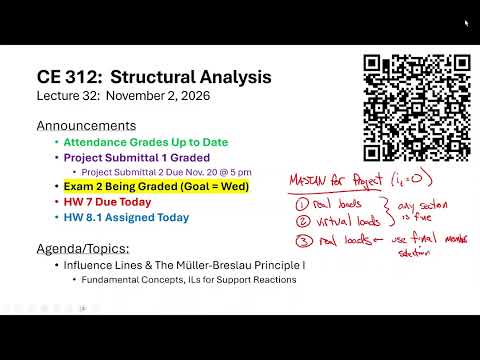
- Project submittal two uses real-load, virtual-load, and final real-load analyses in Mastan; for the statically determinate trusses, section choices change deflections but not member forces.
Chapters
- Project submittal two is due November 20 at 5:00 p.m. and requires member sizing for both strength and midspan deflection.
- Use Mastan for three analyses: real loads with any sections, virtual loads with any sections, and real loads with final member selections.
- Because the trusses are statically determinate, changing member sections changes deformations but not member forces; IT = 0.
- Submit the Mastan model, Excel calculations, drawing, and a short reflection on what you would change if repeating the project.
- The remaining major topics are influence lines and matrix analysis, including the principles behind how Mastan solves models.
- Moving bridge loads make ordinary shear and moment diagrams inconvenient because each new load position changes the reactions and diagrams.
- Influence lines provide a tool for assessing moving-load effects and identifying critical load placements.
- A project analysis Q&A is planned for November 20; students who submit early do not need to attend.
- An influence line tracks one fixed response, such as a reaction, shear, or moment, while a unit load moves across the structure.
- Its plotted ordinates give the response to a unit load at each position; a load of 5 kips produces five times the unit-load response.
- Unlike a shear or moment diagram, an influence line keeps the point of interest stationary and moves the load.
- For an 80-ft simply supported beam, the influence line for reaction A decreases linearly from 1 at A to 0 at the opposite support.
- Influence lines for statically determinate structures are linear between locations where structural conditions change.
- A curved influence-line sketch for a determinate structure signals an error in the construction.
- The linearity makes slope ratios a fast way to calculate ordinates between known values.
- Indeterminate structures do not necessarily have linear influence lines, a distinction reserved for later discussion.
- The Müller-Breslau principle states that the displaced shape of a structure represents its influence line to scale.
- First identify the response of interest, such as a support reaction or an internal shear or moment.
- Remove the structure's ability to resist that response, then impose a unit displacement at the released location.
- The resulting mechanism shape gives a graphical influence-line construction; the lecture focuses on reactions before treating shear and moment.
- For the example beam with supports A, B, and C and an internal hinge, releasing a reaction turns the structure into linked rigid segments.
- Lifting the released support shows how the remaining supports and hinge constrain the shape, including segments that rotate without bending.
- A reaction influence line has ordinate 1 at its support of interest and 0 at the other vertical supports.
- At any load position, the vertical reaction influence-line ordinates sum to 1 because a unit vertical load must be balanced.
- For the beam supported at A and C with no internal hinge, releasing A makes the beam rotate as one rigid link about C.
- The reaction A influence line has value 1 at A and 0 at C; its straight segments extend according to the beam geometry.
- Releasing C similarly produces the reaction C influence line, with 0 at A and 1 at C.
- Using a 30-ft reference run, the reaction A line gives ordinates of 1/3 and -1/3 at the indicated points; a unit load at D confirms Cy = 4/3 and Ay = -1/3.
- For the two-span beam with a hinge between A and B, Michaelson constructs separate influence lines for reactions Ay, By, and Cy.
- Each reaction line takes values 1 at its own support and 0 at the other supports.
- The internal hinge divides each influence line into piecewise straight segments; some segments, such as part of the Ay line, remain at zero.
- The By line rises toward the hinge and falls afterward, while the Cy line descends and then rises across the spans.
- Use similar triangles to calculate unknown ordinates from a known rise and run; the example uses a rise of 1 over a 20-ft run.
- The illustrated intermediate values include 6/20 = 0.3, 14/20 = 0.7, and 28/20 = 1.4; the corresponding opposite ordinate is -0.4.
- Two influence-line problems are assigned for Wednesday, when the class will apply the method to shear and moment at a point of interest.
- The lecture stresses drawing the shapes first and then calculating their ordinates systematically.
Transcript excerpt
0:03 Well, a new projector and we can see what's going on on the screen. It's fantastic. I love it. Pretty good. Okay. All right, everybody. Um So, uh just a couple of housekeeping items. Everybody should uh have received their project one grade report. Um project submittal two is due uh on November 20th at 5:00 p.m. Okay? Now, um since everybody just did homework number seven, okay? I want to give you a little bit of a hint on submittal number two and I think that now that you've done
0:52 homework seven, you'll receive that that hint a little bit more uh clearly today. So, So, let's just talk about submission two for the project, okay? So, what you're going to do in submittal two is as follows. In submission one, you uh um laid out three trusses and then you picked one for final design, okay? So, in submission two, you're going to take that truss and you're going to select members for that truss such that they meet both strength requirements and deflection requirements. Remember the strength requirements, you calculate sigma equals P over A and make sure that those stresses are less than the assigned materials uh value for the um for the project and then the deflection, you just limit that midspan deflection,
1:41 okay? So, what that means is that you're going to have to analyze the truss a number of times, okay? So, I propose that you're going to need to do um basically three analyses, okay? So, >> So, what that means is you're really going to need to do three different sets of analyses, okay? So, one is the real loads, two is the virtual loads, and three is the real loads again, and
2:29 let me explain what I mean. Okay. So, like I said, you're not going to
This is the start of the transcript. Save this video free for the whole transcript, searchable and time-coded.
In this course
Related notes
Summary, takeaways, and chapters were generated by AI from the video's transcript and may contain errors. The video belongs to its creator, Gregory Michaelson.