CE 312 Lecture 33: Influence Lines II, Shear/Moment ILs (2026.11.04)
 Watch on YouTube →
Overview
Gregory Michaelson applies the Müller-Breslau principle to construct influence lines for internal shear and moment in statically determinate beams. He establishes sign and geometry rules, works through two beam examples with numerical ordinates, and shows how influence-line signs identify where moving traffic loads create worst-case positive or negative responses.
Key takeaways
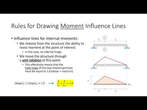
- For an internal moment influence line, release moment at the section and impose a unit rotation, so the adjoining segment slope changes sum to 1.
- For an internal shear influence line, impose a unit vertical jump while retaining moment resistance, which requires equal slopes on the two sides of the shear release.
- Internal shear and moment influence lines are zero at supports, linear on statically determinate spans, and change slope at internal hinges.
- For the first beam's shear at B, spans of 20 ft and 10 ft produce magnitudes 2/3 and 1/3 when equal slopes and a unit jump are enforced.
- To find extreme moving-load effects, place traffic only over the positive influence-line regions for a worst positive response, or over negative regions for a worst negative response.
- For the section 1 practice beam, the demonstrated shear ordinates include -0.7, +0.3, and 0.4 at the hinge, while the moment ordinates include +4.2 and -2.4.
Chapters
- Gregory Michaelson introduces internal-response influence lines as the lecture's focus, following earlier work on reaction influence lines.
- He notes that Exam 2 is still being prepared and Homework 8.1 was intended to be a short assignment.
- Influence lines provide an alternative method for analyzing structures under moving loads.
- An influence line records a response as a unit load moves across the structure; each line represents one response of interest.
- For reaction influence lines, the ordinate is 1 at the selected reaction and 0 at other reactions.
- In statically determinate structures, influence-line segments are linear, and internal hinges change their slope.
- A beam with an internal hinge can be viewed as connected rigid links, which explains why the influence line changes direction at the hinge.
- A shear influence line has a jump at the section: its left side trends downward and its right side trends upward under the course sign convention.
- A moment influence line peaks at the section of interest, with adjacent slopes reflecting the positive moment directions on left and right cuts.
- Internal shear and moment influence lines are zero at supports because a load placed directly over a support produces no internal response elsewhere in the beam.
- Bridge engineers may calculate influence lines at about 10 points along a span; symmetry can reduce the number of distinct sections required.
- To construct a moment influence line, release the beam's ability to resist moment at the section by inserting a hinge.
- Apply a unit rotation at that hinge; the total change in slope across the release must equal 1.
- For straight-line segments, calculate the needed ordinate from rise-over-run slopes, then use linearity to determine the remaining values.
- A shear release allows vertical displacement across the section while retaining moment resistance, unlike a moment-release hinge.
- For a unit shear displacement, the jump across the release totals 1, while the two adjoining segments retain equal slopes.
- Internal response influence lines are zero at reactions, linear for statically determinate structures, and change slope at internal hinges.
- Michaelson illustrates both releases as mechanisms made from rigid beam segments, with the release location guiding the deformation.
- For shear at B, the ordinates at supports A and C are zero; the shear-release shape trends down to the left and up to the right.
- The adjacent segments span 20 ft and 10 ft, so equal slopes require H1/20 = H2/10.
- With H1 + H2 = 1, the magnitudes are H1 = 2/3 and H2 = 1/3, producing ordinates of -2/3, +1/3, and -1/3 across the illustrated segments.
- For a 500 lb/ft traffic load, the worst positive shear at B comes from loading only the region with positive influence-line ordinates.
- The worst negative shear comes from loading the regions with negative ordinates, rather than loading the entire bridge uniformly.
- This sign-based placement identifies load cases that engineers must check when designing a beam for moving traffic.
- To obtain the moment influence line at B, Michaelson inserts a moment release there and rotates the adjoining beam segments while keeping support ordinates at zero.
- For the illustrated 20 ft and 10 ft segments, the slopes satisfy h/20 + h/10 = 1, giving h = 20/3 ft, or about 6.67.
- The resulting positive and negative regions indicate separate moving-load arrangements for worst-case positive and negative moment.
- The second beam example has three straight-line segments for each influence line: support A to the hinge, hinge to section 1, and section 1 to support C.
- For shear at section 1, the calculated ordinates include -0.7 and +0.3 around the release, with an ordinate of 0.4 at the internal hinge.
- For moment at section 1, the key ordinates are +4.2 at the section and -2.4 on the opposite side; slope ratios determine the hinge value.
- Michaelson recommends starting at the response section and working outward, using the known zero ordinates at supports to establish the shape.
- Michaelson assigns Homework 8.2 for Friday and says Homework 8.4, assigned Monday, will use its answer.
- The solution to Homework 8.2 is scheduled to become available Monday, before students work on Homework 8.4.
- The next class is scheduled to cover cantilever beams.
Transcript excerpt
0:03 Okay, let me close teams. >> So, we can jump right in. Okay. >> All right, everybody. Uh, can you believe this is lecture 33? Can you believe that? >> I'm going to take that personally. No. Um, I was uh I was taking my daughter to school this morning and she said, "Do you have an exam today?" I said, "No." She said, "Well, you should make one." Oh. And then she said, "You should make a real hard one." So, >> she'll learn.
0:50 >> She'll learn. She'll understand. >> Yeah, I know. Okay. Um, I I think everything's current except for exams. Exam two, I'm still working on that. And I'm uh you all just turned in homework 7. I don't think uh that's been posted yet, but I I I checked it I think sometime yesterday. I hadn't checked it this morning. Um, how did homework 8.1 go? Well, I'm hoping it was a fast homework. Okay. So, I I also imagine that uh your first homework of influence line sort of felt like, okay, there's this puzzle, but what's the point? Okay, it's going to feel that way for a little bit. And so, just sort of trust me on this, but when we start using influence lines, I think you'll
1:38 go, "Oh, okay. Now I see the point." Okay? Because, uh, it presents an entirely different way of doing structural analysis. And um when you see how we employ it for moving loads um some of the work will be tedious but then if you sort of think okay if we had to do it without influence lines it would be so much worse. So um it does have a way of speeding up analyses uh and what have you. Um so what we're going to do today is continue on our
This is the start of the transcript. Save this video free for the whole transcript, searchable and time-coded.
In this course
Related notes
Summary, takeaways, and chapters were generated by AI from the video's transcript and may contain errors. The video belongs to its creator, Gregory Michaelson.