NDSU ECE 211 Lecture 27
Overview
Roger Green develops the sinusoidal basics needed for steady-state circuit analysis, defining peak amplitude, phase, period, frequency, and the relationship ω = 2πf. He derives RMS voltage from average power, showing that a sinusoid has V_RMS = V_M/√2 and that a 120 V, 60 Hz U.S. outlet reaches about 170 V peak; a same-peak sawtooth has V_RMS = V_M/√3 and delivers less average power to a 50 Ω load.
Key takeaways
- A sinusoid's angular frequency and ordinary frequency are related by ω = 2πf, while its period is T = 1/f.
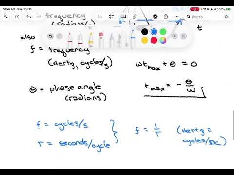
- For v(t) = V_M cos(ωt + θ), the nearest maximum occurs at t = -θ/ω; convert phase angles in degrees to radians before evaluating the cosine.
- RMS voltage is defined as the square root of the period-average of v²(t), making average resistor power P_avg = V_RMS²/R.
- A sinusoid has V_RMS = V_M/√2, so a 120 V RMS, 60 Hz outlet reaches approximately 170 V peak.
- At the same 170 V peak and across 50 Ω, a sinusoid delivers 288 W average, while the sawtooth example delivers about 192.6 W because its RMS value is lower.
Chapters
- RLC circuit responses combine a forced particular solution and a natural complementary solution.
- Natural responses in RL and RC circuits typically decay; after roughly five time constants, the persistent forced response is often the main interest.
- Sinusoidal sources are common in power systems, and Fourier analysis can extend sinusoidal understanding to more general signals.
- The general voltage form is v(t) = V_M cos(ωt + θ), where V_M sets the positive and negative peaks.
- Angular frequency ω is measured in radians per second, while phase angle θ is measured in radians.
- A nonzero θ shifts the waveform in time; the closest maximum occurs at t_max = -θ/ω.
- The period T is the time for one complete cycle, and frequency in hertz is f = 1/T.
- Because cosine repeats every 2π radians, one cycle gives ωT = 2π and therefore ω = 2πf.
- The equivalent signal form v(t) = V_M cos(2πft + θ) keeps the cosine argument in radians.
- Phase can be expressed in degrees for convenience, but it must be converted to radians before use in a cosine argument.
- For v(t) = 3 cos(6πt - 60°), the phase converts to -π/3 radians, the peak magnitude is 3 V, and ω = 6π rad/s.
- Using ω = 2πf gives f = 3 Hz and T = 1/3 s; the nearest positive peak occurs at t = 1/18 s.
- For the 3 Hz example, marking the period in sixths places the first maximum at T/6 and the negative peak half a period later.
- Using either sine or cosine consistently avoids ambiguity when combining sinusoids; cosine is recommended for later phasor work.
- The identity sin(a) = cos(a - π/2) converts sine signals to cosine form with a 90° phase shift.
- For a voltage applied to a resistor R, instantaneous power is p(t) = v²(t)/R.
- Average power over one period is P_avg = (1/T)∫₀ᵀ p(t)dt.
- Defining V_RMS = √[(1/T)∫₀ᵀ v²(t)dt] makes the power relation P_avg = V_RMS²/R.
- U.S. mains power is modeled as a 60 Hz sinusoid; the familiar 120 V rating refers to its RMS value, not its peak.
- For current, the analogous definition is I_RMS = √[(1/T)∫₀ᵀ i²(t)dt], giving P_avg = I_RMS²R.
- The sinusoidal RMS derivation uses cos²(a) = [1 + cos(2a)]/2; the doubled-frequency cosine averages to zero over a full period.
- Integrating the constant half of the cosine-squared identity yields V_RMS = V_M/√2 for a sinusoid.
- A 120 V RMS outlet therefore has a peak voltage of 120√2 ≈ 170 V, or about 340 V peak-to-peak.
- Across a 50 Ω resistor, the outlet delivers average power of 120²/50 = 288 W.
- The comparison waveform keeps the outlet example's 60 Hz period and approximately 170 V peak magnitude but uses a linear ramp instead of a sinusoid.
- Over one period, the ramp is expressed as v(t) = (2V_M/T)t - V_M, rising from -V_M to +V_M.
- Its RMS value is found from the same definition, integrating the squared ramp over one period.
- Squaring and integrating the sawtooth ramp gives V_RMS = V_M/√3, compared with V_M/√2 for a sinusoid.
- With V_M = 170 V, the sawtooth RMS value is about 98.15 V, below the sinusoid's 120 V RMS.
- For a 50 Ω load, the sawtooth delivers about 192.6 W, less than the sinusoid's 288 W, showing that waveform shape affects average power at equal peak voltage.
Transcript excerpt
0:02 Welcome to NDSU ECE211. This is lecture 27. Last time we did an example solving an RL circuit that had a general source. Today we're going to switch gears and work towards really the last topic of the semester, which is sinosoidal steady state analysis. This is going to require us to investigate um concepts that are called phasers and complex impedance. But underlying all of those is an understanding of sinosoids. So really um sinosoidal steady state analysis uh begins with this understanding that circuits with resistors, inductors and capacitors and described by differential equations have a solution which has a particular solution and a complimentary solution. We've seen that in our previous studies that particular
0:49 solution is uh connected to the forcing function um or the forced response and the complimentary solution is connected to how the circuit uh naturally wants to release energy or the natural solution. Usually that natural solution decays away. Um for example an RL circuit and RC circuit have a time constant that we know after about five time constants. um a charged capacitor or a inductor with an initial current essentially discharge completely leaving no energy in it if they were hooked up to a resistor. So um that natural response has a tendency to decay and it um leaves then really only the forced solution uh that might persist for a long time. As a result um it's often times that forced response that is of most interest. This isn't
1:36 always the case, but often times it is the case uh that we're more interested in that persistent response rather than the the transient which can disappear very quickly. Um we're going to look in this particular uh chapter or this particular time at the common case of sinosoids as our is our forcing function
This is the start of the transcript. Save this video free for the whole transcript, searchable and time-coded.
In this course
Related notes
Summary, takeaways, and chapters were generated by AI from the video's transcript and may contain errors. The video belongs to its creator, Roger Green.