NDSU ECE 211 Lecture 12
 Watch on YouTube →
Overview
Roger Green explains superposition for linear resistive circuits, finding each independent source's contribution separately and adding the resulting voltages or currents; independent voltage sources are replaced by shorts and independent current sources by opens, while dependent sources remain active. Examples calculate a 10 V, 2 A circuit's total resistor voltage and current, then analyze a dependent-source circuit to obtain I = -8/23 A. The lecture also derives practical-source transformations, showing how a 2 A source with 3 Ω in parallel can become a 6 V source with 3 Ω in series, and then a 1.5 A source with 4 Ω in parallel after combining a series resistor.
Key takeaways
- For linear resistive circuits, superposition finds total voltage or current by summing each independent source's contribution calculated with all other independent sources zeroed.
- Zero an independent voltage source by replacing it with a short, and zero an independent current source by replacing it with an open; do not zero dependent sources.
- In the first example, the 10 V source contributes 10/3 V and 2/3 A, while the 2 A source contributes 20/3 V and -2/3 A, producing 10 V and 0 A overall.
- Source transformations preserve terminal behavior when the voltage-source series resistance equals the current-source parallel resistance and VS = IS × RT.
- A 10 V source with 0.1 Ω internal series resistance is equivalent to a 100 A source with 0.1 Ω parallel resistance.
- The final network's 2 A source with 3 Ω in parallel and 1 Ω in series is equivalent to a 6 V source with 4 Ω in series, or a 1.5 A source with 4 Ω in parallel.
Chapters
- For a circuit with n independent sources, find an element's response to each source with the other independent sources zeroed.
- The total response is the sum of individual responses, such as resistor voltage or branch current.
- The method applies to linear resistive circuits; Ohm's law and linear dependent-source relationships satisfy the required linearity.
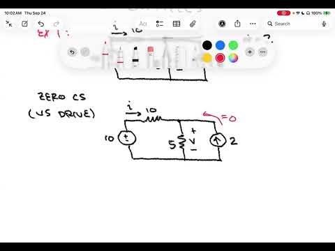
- The example has a 10 V source, 10 Ω and 5 Ω resistors, and a 2 A current source; the quantities of interest are current I and the 5 Ω resistor's voltage V.
- Zeroing the independent 2 A current source means removing it and leaving an open circuit.
- With only the 10 V source active, the 10 Ω and 5 Ω resistors are in series, so voltage division gives V1 = 10/3 V and I1 = 2/3 A.
- Zeroing the 10 V source means replacing it with a short circuit, leaving the 10 Ω and 5 Ω resistors in parallel across the 2 A source.
- The parallel equivalent is 10/3 Ω, giving V2 = 20/3 V across the 5 Ω resistor.
- Current division with the stated reference direction gives I2 = -2/3 A; adding source responses yields V = 10 V and I = 0 A.
- With both sources active, the left-mesh equation reduces to 3I1 - I2 = 2, while the right mesh's 2 A source sets I2 = -2 A.
- Substitution gives I1 = 0 A, matching the superposition result for the 10 Ω branch current.
- The 2 A flowing through the 5 Ω resistor produces V = 2 × 5 = 10 V, confirming the superposition voltage.
- The circuit contains a 10 V independent voltage source, a 3 A independent current source, a 5 Ω resistor carrying I, a dependent 2I current source, and a 6 Ω resistor.
- Only the two independent sources create separate superposition cases; the dependent source remains in the circuit in both cases.
- With the 3 A source opened, a supermesh and KCL give 10 = 5I + 18I, so the voltage-source contribution is I1 = 10/23 A.
- With the 10 V source replaced by a short, node-voltage expressions across the 5 Ω and 6 Ω resistors give -5I = 6(3I + 3).
- Solving gives the 3 A source contribution I2 = -18/23 A, with the sign determined by I's reference direction.
- Superposition gives I = I1 + I2 = 10/23 - 18/23 = -8/23 A.
- A practical voltage source is modeled as an ideal voltage source in series with internal resistance, unlike an ideal battery that maintains voltage without limit.
- A practical current source is modeled as an ideal current source in parallel with internal resistance.
- Connecting the same load to two source models tests equivalence: both must produce the same load voltage and current.
- For the practical voltage-source model, the ideal source voltage VS equals the open-circuit voltage measured across terminals A and B.
- For the practical current-source model, the ideal source current IS equals the short-circuit current across A and B.
- With a load RL attached, the voltage-source model uses voltage division and the current-source model uses current division to determine load voltage.
- The voltage-source load voltage is VS × RL/(RS + RL); the current-source load voltage is IS × RP × RL/(RP + RL).
- Matching these expressions for the same load requires equal internal resistances, RS = RP = RT, and VS = IS × RT.
- A 10 V practical source with 0.1 Ω series resistance transforms to a 100 A current source with 0.1 Ω parallel resistance.
- The initial two-terminal network has a 2 A current source in parallel with 3 Ω, followed by a 1 Ω series resistor.
- Transforming the 2 A and 3 Ω pair gives a 6 V source in series with 3 Ω; combining the 1 Ω resistor produces a 6 V source with 4 Ω series resistance.
- Transforming that practical voltage source gives a 1.5 A source with 4 Ω parallel resistance, since 6 V / 4 Ω = 1.5 A.
- Each form has equivalent behavior at terminals A and B, and the lecture previews reducing larger source-resistor networks to one practical source.
Transcript excerpt
0:01 Welcome to ND issue ECE211. This is lecture 12. Last time we finished our discussion of mesh current analysis, including the idea of super meshes, and we did several examples. Today I'd [clears throat] like to begin by introducing something called the superp position principle. This is something really um that is useful for resistive circuits which have n independent sources. N is some number usually greater than one. it makes most sense or has most application when multiple sources are present. We've seen in previous examples when we have multiple sources present um it can complicate our overall analysis. The superp position principle offers a alternative way of approaching those problems. It's a divide and conquer kind of approach. Let's see how it works. So our resistive circuit with n sources and
0:49 independent sources. What I'd like to do is I'd like to say um let's go ahead and let little s r subn be the response. So little r subn be the response of some element some element in our circuit. That could be things like a resistor for example. And we're going to let it be the response of some element to source little n. Little n is drawn from the total number of sources available that can go all the way up to n. And it's the response to that source n with the remaining
1:40 cap n minus one sources. zeroed. So, in other words, I have a bunch of sources in a circuit and there's some element that I'm interested in what's going on with it. Um, let's say it's a resistor. Let's say the thing we're interested in is the voltage. Um, we are going to take a divide and conquer approach to the circuit. And essentially what we're going to do is we're going to
This is the start of the transcript. Save this video free for the whole transcript, searchable and time-coded.
Related notes
Summary, takeaways, and chapters were generated by AI from the video's transcript and may contain errors. The video belongs to its creator, Roger Green.