NDSU ECE 211 Lecture 13
 Watch on YouTube →
Overview
Roger Green explains Thevenin and Norton equivalents as ways to replace a two-terminal network of resistors and sources with a practical voltage source or current source. A worked circuit with a 10 V source, a 1 A source, and resistors of 1 Ω, 6 Ω, and 3 Ω yields VTh = 66/7 V and RTh = 27/7 Ω, then establishes the maximum-power-transfer condition RL = RTh.
Key takeaways
- A two-terminal linear resistor-source network can be replaced by either a Thevenin source VTh in series with RTh or a Norton source IN in parallel with the same resistance.
- Measure VOC with the output open and ISC with the output shorted; then RTh = VOC/ISC and IN = ISC.
- For direct calculation of equivalent resistance, zero independent sources: replace voltage sources with shorts and current sources with open circuits, then find the resistance seen at the output terminals.
- In the worked circuit, VOC = 66/7 V, ISC = 22/9 A, and both source models have an equivalent resistance of 27/7 Ω.
- Maximum power transfer to a resistive load occurs when RL = RTh; the result follows from maximizing PL = VT²RL/(RT + RL)².
Chapters
- A practical voltage source consists of an ideal voltage source in series with resistance; a practical current source has resistance in parallel.
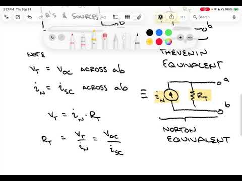
- Thevenin represents a two-terminal resistor-source network as a voltage source VTh in series with RTh.
- Norton represents the same network as a current source IN in parallel with the same equivalent resistance RTh.
- Dependent sources are allowed when all variables controlling them remain within the two-terminal network.
- Thevenin voltage VTh equals the open-circuit terminal voltage VOC across terminals A and B.
- Norton current IN equals the short-circuit current ISC through A and B.
- Source transformation gives VTh = IN × RTh, so RTh = VOC/ISC when both measurements are available.
- To find RTh directly, zero independent voltage sources by shorting them and zero independent current sources by removing them and leaving open circuits.
- The example network uses a 10 V source, R1 = 1 Ω, R2 = 6 Ω, R3 = 3 Ω, and a 1 A current source, with output terminals A and B.
- With A and B open, R3 carries no current, and the external current source sets mesh current I2 = -1 A under the chosen directions.
- Mesh analysis gives 10 = I1 + 6(I1 - I2), resulting in I1 = 4/7 A.
- The open-circuit voltage is VOC = 10 - I1R1 = 66/7 V, approximately 9.4286 V.
- Shorting terminals A and B creates a third mesh, so the short-circuit case includes currents I1, I2, and I3.
- The current source lies between meshes 2 and 3, so Green uses a supermesh around both loops and adds the constraint I3 - I2 = 1 A.
- The resulting equations are 7I1 - 6I2 = 10 and -6I1 + 9I2 = -3.
- Solving gives I1 = 8/3 A and I2 = 13/9 A; the short-circuit current is ISC = I3 = 1 + I2 = 22/9 A.
- Using the open- and short-circuit results, RTh = VOC/ISC = (66/7)/(22/9) = 27/7 Ω.
- For the direct resistance method, short the 10 V source and remove the 1 A source, leaving its branch open.
- Looking into A and B, the remaining network is R3 in series with R1 parallel to R2.
- RTh = (1 Ω || 6 Ω) + 3 Ω = 6/7 + 3 = 27/7 Ω, confirming the measurement-based result.
- The Norton current is IN = ISC = 22/9 A for the example network.
- The Norton resistance is the same as the Thevenin resistance, RN = RTh = 27/7 Ω.
- The equivalent Norton circuit is a 22/9 A current source in parallel with 27/7 Ω across terminals A and B.
- The relation VTh = IN × RTh reproduces 66/7 V, confirming consistency between the two equivalents.
- A Thevenin source VT with internal resistance RT drives a load resistance RL in a single series loop.
- The load current is IL = VT/(RT + RL), by Ohm's law.
- Substituting into PL = IL²RL gives PL = VT²RL/(RT + RL)².
- Because Thevenin and Norton forms are equivalent, the same maximum-power condition applies to either source representation.
- Differentiate PL = VT²RL/(RT + RL)² with respect to RL and set the derivative to zero to find the extremum.
- After canceling common factors, the condition reduces to RT + RL = 2RL.
- Therefore, maximum power reaches the load when RL = RT, meaning the load resistance matches the source's Thevenin resistance.
- The maximum-power result applies to the example when the load is set to 27/7 Ω.
- The lecture concludes the current unit on DC resistive circuit analysis and notes that the textbook's delta-wye section will not be covered.
- The next topic is operational amplifiers, followed by capacitor and inductor circuit analysis.
Transcript excerpt
0:01 Welcome to the issue ECE211. This is lecture 13. Last time we talked about the superp position principle. We also introduced practical sources. That's a voltage source or a current source with some added resistance. For the voltage source, that resistance was in series. For the current source, that resistance was in parallel. We also talked about the equivalence between those practical sources and then use that equivalence to consider um source transformations. basically turning a practical voltage source into a practical current source. The last example that we gave um did something beyond just a simple voltage source or current source. We had a current source with an extra resistor in it. And we went ahead and still went through source transformations to convert that into a purely practical voltage source and then in turn also a
0:49 purely practical current source. We can generalize this idea. Basically, the idea is that you have a two terminal network um where the network itself is a is a collection of sources and resistors. And we're going to replace that entire network, that entire collection of of resistors and sources with um our our practical voltage source or practical current source. This is something called the thean and Norton equivalents. So today we're going to talk thean and Norton equivalents. So what is thean and Norton equivalents? It's the replacement of any two terminal block box if you will combination of resistors and sources. Um the sources themselves can be independent sources. They can also be dependent sources if all dependencies everything that defines
1:37 that dependent source is fully within that that network box. Um and we're going to replace these with our practical source equivalents. If it's the voltage and series resistance, that's going to be called the thean equivalent. And if it's the current with
This is the start of the transcript. Save this video free for the whole transcript, searchable and time-coded.
Related notes
Summary, takeaways, and chapters were generated by AI from the video's transcript and may contain errors. The video belongs to its creator, Roger Green.