EAS4200 Aerospace Structures, Lecture 4, 2026 fall
Overview
Ting Dong develops a coordinate-based description of stress at a point, showing how the normal and shear stresses on the X, Y, and Z planes form a 3×3 stress matrix. He establishes a plane-and-direction sign convention, derives shear-stress symmetry from moment equilibrium, and begins deriving the relation between stress, a plane’s unit normal, and surface traction in 2D.
Key takeaways
- A stress state at a point can be specified using the normal and shear stress components on three coordinate planes, organized as a 3×3 matrix rather than listing stresses on every possible plane.
- The sign of a stress component depends on both the plane normal and the component direction: matching signs produce positive stress, while opposing signs produce negative stress.
- Moment equilibrium on a small cube requires paired shear components to be equal, so τxy = τyx, τyz = τzy, and τxz = τzx; the stress state therefore has six independent components.
- Uniaxial tension has one nonzero normal component, while hydrostatic compression has equal negative normal stresses on all three matrix diagonals and zero shear components.
- Plane stress is a useful approximation for thin fuselage skin when in-plane hoop and longitudinal stresses greatly exceed thickness-direction stress.
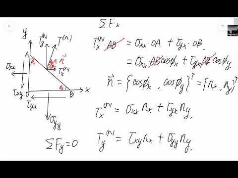
- In 2D, surface traction on a plane with unit normal (nx, ny) is obtained by multiplying the stress matrix by that normal: tx = σxx nx + τyx ny and ty = τxy nx + σyy ny.
Chapters
- Students record their own printed name, UFID, and signature for attendance credit.
- The preceding lecture connected surface traction and a plane’s unit normal to normal and shear stress components.
- A unit normal has components equal to direction cosines, with squared components summing to 1.
- A small cube around a point replaces descriptions of stresses on infinitely many rotated planes with stresses on the X, Y, and Z coordinate planes.
- The traction on each coordinate plane has three components, one in each of the X, Y, and Z directions.
- In Ting Dong’s notation, the first stress subscript identifies the plane and the second identifies the component direction.
- The X-plane components are σxx, τxy, and τxz; the Y-plane components are τyx, σyy, and τyz.
- The Z-plane components are τzx, τzy, and σzz, giving nine entries in the stress matrix.
- Normal stresses occupy entries where plane and direction match, while off-diagonal entries represent shear stresses.
- A positive or negative plane is identified by the direction of that plane’s normal vector, such as the positive X face or negative X face.
- A stress component is positive when its plane and direction signs match: positive-positive and negative-negative are both positive.
- A component is negative when plane and direction signs differ, including positive-plane/negative-direction and negative-plane/positive-direction cases.
- Tensile normal stress points outward on opposite faces and is positive on both the positive and negative X planes.
- Compressive normal stress points inward and is negative on both opposite faces.
- For a shear example, τxy is positive on the positive X plane in the positive Y direction, and remains positive on the negative X plane in the negative Y direction.
- Ting Dong considers a small cube in equilibrium and balances moments generated by the shear components τxy and τyx.
- With equal face areas A and edge length ΔL, the opposing moment terms are AτxyΔL and AτyxΔL, so τxy = τyx.
- Applying the same argument to the other plane pairs gives τyz = τzy and τxz = τzx, reducing nine matrix entries to six independent stress components.
- Uniaxial tension in the X direction has σxx as its only nonzero stress-matrix component.
- Hydrostatic pressure applies equal compressive normal stress to all six cube faces, represented by equal negative diagonal entries and zero shear entries.
- For a pressurized fuselage skin, hoop and longitudinal stresses can dominate thickness-direction stress, motivating a plane-stress approximation with Z-direction components set to zero.
- The 2D derivation uses an inclined plane in the XY coordinate system, with unit-normal components nx and ny.
- The surrounding faces carry σxx, σyy, τxy, and τyx, and the inclined face has traction components in X and Y.
- Force equilibrium is written by multiplying each stress or traction by its loaded edge area, including the common thickness T.
- The X-direction equilibrium gives tx = σxx nx + τyx ny after substituting the plane’s direction cosines and cancelling common area factors.
- The Y-direction equilibrium gives ty = τxy nx + σyy ny.
- The equations combine as [tx, ty]ᵀ = [[σxx, τyx], [τxy, σyy]][nx, ny]ᵀ; extending the derivation to 3D is left for the next class.
Transcript excerpt
0:00 Write down your name, your UFID, and signature. So, also on that side. Uh we're we start taking attendance start from today. So, uh I will need I have one visitor here, and then uh you guys need to write down your name, your UFID, your UFID, and signature. Um Do not write your name the name of your friend um or your classmate or uh you can only write down the name of yourself. Make sure the first first one first column is the uh print your name so TA can recognize your handwriting and know who you are. So, we can give you the extra credit for the attendance. Uh so, uh your printing name, UFID, signature. You can only write down your own name. Um
1:04 Um so, in the last class, we talked about the um surface traction, and we explained that if the surface uh for the surface traction, uh when we cut a surface structure of a certain point, when we rotate the point, the surface traction is different because the plane is different. Um and we talked about how to identify the unit normal vector of a plane. And if we know the surface traction and the unit normal vector, we can find the normal stress component and shear stress component on our structure. And this is becomes this becomes a very important for our structure of class because if we can find the normal stress and shear stress, we can base on the uh use it for our failure theory to determine if our structure is safe or not on that specific plane. And we gave an example problem. So,
1:52 basically, surface traction was given as a vector, and the unit vector you need to identify. Um, so, the rest part is just calculation.
This is the start of the transcript. Save this video free for the whole transcript, searchable and time-coded.
In this course
Related notes
Summary, takeaways, and chapters were generated by AI from the video's transcript and may contain errors. The video belongs to its creator, Ting Dong.