Aerospace Structure, Lecture 17, 2026 fall
 Watch on YouTube →
Overview
Ting Dong applies the fully reversed S-N fatigue model to a rotating, four-point-bending steel beam, using a 120 ksi ultimate strength, a 0.82 fatigue-strength fraction, and a 60 ksi endurance limit. The worked example estimates fatigue life for a 0.30 in radius beam, then sizes the beam for 100,000 cycles and for modeled infinite life before introducing static and fatigue stress-concentration factors for fastener holes.
Key takeaways
- A fully reversed fatigue cycle has equal tensile and compressive stress magnitudes, making the fully reversed S-N curve applicable to the rotating-beam example.
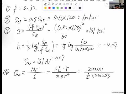
- For the example steel with 120 ksi ultimate strength, the adopted fatigue-strength fraction is 0.82, the endurance limit is 60 ksi, and the approximate S-N parameters are A = 161 ksi and B = -0.07.
- The 2,000 lbf four-point-bending example produces about 94 ksi at a 0.30 in radius, corresponding to approximately 2,000 cycles to failure under the fitted S-N relation.
- At a target life of 100,000 cycles, the example allows about 72 ksi and requires a beam radius near 0.33 in; a radius near 0.35 in reduces stress to the 60 ksi endurance limit.
- Fastener-hole geometry increases local stress, and manufacturing or repair microcracks can provide starting defects for fatigue-crack growth.
- Theoretical static concentration factors Kt and Kts depend on geometric ratios, while fatigue factors Kf and Kfs are typically lower than their static counterparts.
Chapters
0:00
Fully Reversed S-N Curves and Material Parameters
- A fully reversed stress cycle has equal-magnitude tensile and compressive peaks, symmetric about zero stress.
- The S-N relation is modeled as a straight line over the relevant range, with stress S = A N^B.
- The line parameters A and B depend on material properties, including ultimate strength, fatigue-strength fraction, and endurance limit.
3:27
Rotating-Beam Example: Four-Point-Bending Setup
- The worked example uses a steel specimen with ultimate strength of 120 ksi and a circular cross-section.
- A symmetric 2,000 lbf loading and a 1 in moment arm create four-point bending.
- One full rotation counts as one fatigue cycle because a material point alternates between maximum tension and maximum compression.
7:17
Finding Maximum Stress from the Bending Moment
- Because the applied load is transverse, the relevant stress is bending stress, calculated with σ = Mc/I.
- In the constant-moment region between the inner loads, the maximum bending moment is force times the 1 in arm.
- For a solid circular section, the outer-fiber distance is the radius and the area moment of inertia is πr⁴/4.
13:53
Estimating Fatigue Life for the 0.30-Inch-Radius Beam
- For 120 ksi ultimate strength, the example uses a fatigue-strength fraction of 0.82 and an endurance limit of 60 ksi, half the ultimate strength.
- These material inputs produce an approximate S-N relation with A = 161 ksi and B = -0.07.
- A 0.30 in radius gives a maximum bending stress of about 94 ksi; substituting that stress into the S-N relation yields roughly 2,000 cycles to failure.
22:30
Sizing the Beam for 100,000 Fatigue Cycles
- For the design case, the material and its S-N parameters remain fixed while the target life is set to 10⁵ cycles.
- The S-N relation gives an allowable stress of approximately 72 ksi at 100,000 cycles.
- Using the bending-stress equation, the required beam radius is approximately 0.33 in; increasing the radius lowers stress and extends life.
28:50
Infinite-Life Radius Set by the Endurance Limit
- The simplified model treats stress below the endurance limit as infinite life, although Ting Dong notes that real structures do not literally run forever.
- For the example steel, the stress threshold is 60 ksi, so the minimum radius follows by setting bending stress equal to that limit.
- The calculated radius is about 0.35 in, slightly larger than the 0.33 in needed for 100,000 cycles.
34:20
Fastener Holes, Manufacturing Cracks, and Static Stress Concentration
- Aircraft frames and fuselage skins require fastener holes, which raise local stress above nominal bending or pressure-vessel stress.
- Drilling and repair can leave microcracks near holes, creating initial defects that can grow under repeated fatigue loading.
- For static loading, the theoretical concentration factors are Kt for normal stress and Kts for shear stress; they depend on geometric ratios, not overall size or material.
40:57
Fatigue Stress-Concentration Factors and Lecture Wrap-Up
- Fatigue concentration factors use Kf for normal stress and Kfs for shear stress, distinguishing fatigue effects from static Kt and Kts.
- Experimental fatigue factors are generally smaller than their theoretical static counterparts for both normal and shear loading.
- Ting Dong ends the technical discussion by deferring further treatment to the next class; a brief post-class exchange concerns an attendance record for September 2.
Summary, takeaways, and chapters were generated by AI from the video's transcript and may contain errors. The video belongs to its creator, Ting Dong.