EAS4200 Aerospace Structures, Lecture 16, 2026 fall
 Watch on YouTube →
Overview
Ting Dong explains stress-life fatigue analysis using a rotating, four-point-bending beam, where a surface point experiences cyclic tensile and compressive stress as the shaft turns. The lecture defines mean stress, stress range, and amplitude, then develops a simplified, fully reversed S-N model from 1,000 to 10^6 cycles, using estimated material strength and endurance-limit data to fit a log-log line.
Key takeaways
- In symmetric four-point bending, the beam segment between the two applied loads has constant maximum bending moment and therefore contains the critical cross-sections.
- A rotating surface point under constant bending experiences a fully reversed cycle, moving through zero, maximum tension, zero, and maximum compression once per rotation.
- Mean stress, stress range, and stress amplitude are distinct quantities: σm = (σmax + σmin)/2, Δσ = σmax − σmin, and σa = Δσ/2.
- The lecture's simplified S-N model treats the 1,000-to-10^6-cycle interval as elastic high-cycle fatigue and the endurance-limit region beyond 10^6 cycles as infinite life below its stress threshold.
- The introduced S-N equations are valid only for fully reversed loading; aircraft loads that shift the cycle away from zero mean stress require additional treatment.
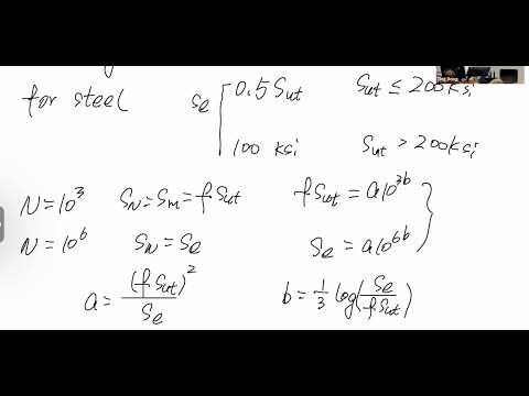
- A log-log S-N power law can be fitted using estimated fatigue strength at 1,000 cycles and endurance limit at 10^6 cycles; for steel, the lecture estimates the endurance limit as 0.5 Sut below 200 ksi and 100 ksi above that threshold.
Chapters
0:00
Four-Point Bending Locates the Beam's Critical Cross-Sections
- For a symmetric four-point-bending beam, bending moment is constant between the two applied loads and decreases linearly toward zero at the supports.
- Because bending stress follows σ = Mc/I, the maximum-moment region between the applied loads contains the critical cross-sections.
- The same cross-section geometry keeps c and I constant along the beam, so the bending-moment diagram identifies where stress is greatest.
6:00
Shaft Rotation Turns Static Bending into Cyclic Surface Stress
- As a beam rotates under constant four-point bending, a surface point moves from the neutral surface to maximum tension, back to neutral, and then to maximum compression.
- One full rotation produces a fully reversed stress cycle with equal tensile and compressive extremes.
- Using y = R sin θ in σ = −My/I explains why the rotating point's stress varies sinusoidally with its angular position.
12:00
Mean Stress, Stress Range, and Aircraft Loading Examples
- Mean stress is σm = (σmax + σmin)/2; stress range is Δσ = σmax − σmin; stress amplitude is half the range.
- The rotating-beam example has zero mean stress because its tensile and compressive peaks are equal in magnitude.
- Fuselage pressurization can cycle tensile stress between a positive in-flight value and approximately zero on the ground.
- A wing-root point can experience flight-induced tension and ground compression from wing, fuel, and engine weight, producing a potentially nonzero mean stress.
17:00
Three Regions of the Idealized S-N Fatigue Diagram
- An S-N diagram relates stress level S to cycles to failure N, with the lecture's simplified model marking 1,000 and 10^6 cycles.
- Below about 1,000 cycles, fatigue deformation combines elastic and plastic components; the lecture sets this low-cycle region aside.
- Between 1,000 and 10^6 cycles, the model uses an elastic high-cycle fatigue regime.
- At the endurance limit, the idealized diagram becomes horizontal, treating lower stress as capable of infinite cycles; the static-failure endpoint may use yield or ultimate strength depending on the failure criterion.
23:00
S-N Design Use Requires Fully Reversed Loading
- The S-N relation lets engineers estimate cycles to failure from stress, or choose a stress limit for a required service life.
- For a specified cycle target, designers can adjust cross-section dimensions so the calculated structural stress stays below the corresponding S-N stress.
- The diagram and equations introduced here apply only to fully reversed loading, where tensile and compressive stress peaks have equal magnitude.
- Fuselage and wing loads with nonzero mean stress cannot use this model directly; Ting Dong flags mean-stress corrections as a later topic.
28:00
Representing the High-Cycle S-N Segment on Log-Log Axes
- The 1,000-to-10^6-cycle segment is treated as a straight line on log-log axes because fatigue life spans large cycle counts.
- Ting Dong writes the power-law form S = A N^B, where A and B are determined from two stress-life data points.
- The selected points are the material strength at 1,000 cycles and the endurance limit at 10^6 cycles.
32:00
Estimating 1,000-Cycle Strength and the Steel Endurance Limit
- The lecture estimates 1,000-cycle fatigue strength as a fatigue-strength fraction times ultimate strength; the example uses a fraction of 0.40.
- The fatigue-strength fraction is based on experimental data and varies with material and ultimate strength.
- For steel, the stated endurance-limit estimate is one-half of ultimate strength below 200 ksi, capped at 100 ksi when ultimate strength exceeds 200 ksi.
- These estimates provide the stress coordinates for the 1,000-cycle and 10^6-cycle points used to fit the S-N line.
36:00
Fit the S-N Power Law from Two Material Data Points
- Substituting the 1,000-cycle strength and the 10^6-cycle endurance limit into S = A N^B gives two equations for the unknown parameters A and B.
- The fitted line can then predict fatigue stress or life within the modeled high-cycle range.
- Ting Dong emphasizes that the derivation is a two-point straight-line fit on logarithmic axes, with material properties supplied by experimental estimates.
Summary, takeaways, and chapters were generated by AI from the video's transcript and may contain errors. The video belongs to its creator, Ting Dong.