ENEE684 Lecture 19
Overview
Ergun Simsek explains how silicon PN-junction ring resonators convert voltage into optical modulation, then develops the operating principles and system tradeoffs of erbium-doped fiber amplifiers (EDFAs) and wavelength-division multiplexing (WDM). Key quantitative examples include ring resonance shifts of roughly 30 to 40 pm, EDFA operation across the C-band near 1550 nm, and the use of amplifier spacing and channel grids to manage optical signal-to-noise ratio and increase fiber capacity.
Key takeaways
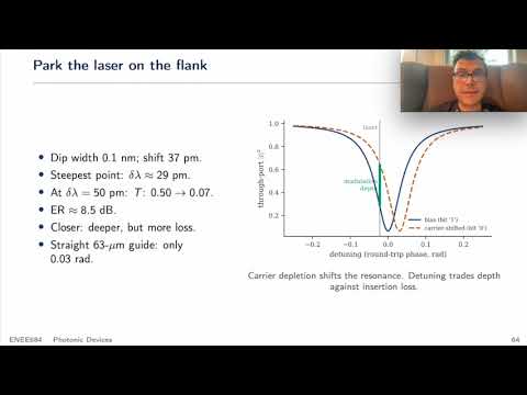
- A silicon ring modulator uses reverse-biased carrier depletion to shift a resonance by roughly 30 to 40 pm, and placing the laser on the resonance flank turns that small shift into a strong intensity modulation.
- Ring-modulator speed depends on both photon lifetime and RC response; reducing loaded Q from values such as 15,500 toward 3,000 to 8,000 improves bandwidth but weakens modulation efficiency.
- Silicon ring resonance can drift about 66 pm per kelvin, so practical devices use heaters and feedback control to keep the resonance aligned with the laser.
- EDFAs amplify many WDM channels together across the C-band near 1550 nm without decoding their bit rate or modulation format, but ASE noise accumulates with each amplifier stage.
- Shorter fiber spans with more frequent EDFAs can preserve OSNR better than fewer, longer spans: the lecture's 2,000 km example estimates about 20 dB OSNR for 100 km spans versus about 3 dB for 200 km spans.
- Flexible-grid WDM assigns channel widths in multiples of 12.5 GHz with centers on a 6.25 GHz grid, allowing bandwidth allocation to match channel needs rather than enforcing uniform spacing.
Chapters
- A silicon ring, typically 5 to 10 μm in radius, couples to a bus waveguide across a gap of a few hundred nanometers.
- A rib-waveguide slab provides electrical access to the P-N junction; heavily doped P+ and N+ regions supply contacts.
- Small device capacitance reduces charging energy, typically to a few or tens of femtojoules per bit; an integrated heater provides thermal tuning.
- Reverse bias widens the depletion region and removes free carriers from the waveguide, changing silicon's effective refractive index through plasma dispersion.
- The resonance condition depends on effective index and round-trip path length, so an index change shifts the resonant wavelength by roughly 30 to 40 pm in the stated example.
- A fixed-wavelength laser converts that resonance shift into an intensity change, allowing electrical data to be written onto an optical carrier.
- Biasing the laser on the steep flank of the resonance dip makes a small wavelength shift produce a large transmission change.
- In the example, a 37 pm shift changes transmission from about 50% to 7%, corresponding to an extinction ratio of roughly 8.5 dB.
- Moving the laser closer to the dip center can deepen modulation but increases insertion loss; ring recirculation enhances the phase effect compared with a straight 63 μm waveguide.
- Photon lifetime limits modulation bandwidth to approximately 1/(2πτ), while the electrical drive adds an RC limit; the combined 3 dB bandwidth follows the reciprocal-square combination of both limits.
- A loaded quality factor of 15,500 gives about 12.5 GHz photon-lifetime bandwidth, while faster designs target loaded Q values around 3,000 to 8,000.
- Lower Q improves speed but broadens the resonance and weakens modulation for a given voltage; silicon resonance also shifts about 66 pm/K, motivating heaters and feedback locking.
- Mach-Zehnder modulators are typically 1 to 5 mm long, support broad wavelength ranges, and can achieve nearly zero chirp with push-pull drive, but consume more energy per bit.
- Ring modulators are compact, typically 10 to 20 μm across, and efficient, but operate around a narrow resonance and require thermal stabilization.
- Rings suit short-reach links and integrated WDM; cascaded rings can create flatter passbands, while paired rings use the Vernier effect to increase effective free spectral range.
- At 1550 nm, standard fiber loss is about 0.2 dB/km, so 100 km produces roughly 20 dB loss and leaves about 1% of the input optical power.
- Optical-electrical-optical regenerators must detect and retransmit signals and are tied to particular wavelengths, bit rates, and modulation formats.
- Erbium-doped fiber amplifiers enabled wavelength-independent optical boosting across roughly 40 nm of spectrum, supporting WDM long-haul systems.
- An EDFA commonly uses an input isolator, a wavelength-division coupler, an erbium-doped fiber section, pump lasers, a gain-flattening filter, and an output isolator.
- Pump wavelengths include 980 nm and 1480 nm; they energize erbium ions so the 1530 to 1565 nm C-band signal can be amplified.
- Erbium-doped fiber lengths are commonly around 5 to 30 m, and the C-band and L-band align with low-loss telecom windows near 1550 nm.
- Erbium is a rare-earth element whose optically active 4f electrons are shielded by outer electron shells, so the glass environment only weakly perturbs their transitions.
- Stark splitting creates groups of sublevels, including the metastable 4I13/2 level that supports emission near 1550 nm.
- A 980 nm pump excites ions to a higher level, followed by relaxation into the metastable state; 1480 nm pumping can also populate the upper amplifier level.
- Spontaneous emission releases a photon without an incoming signal and occurs randomly; erbium's excited-state lifetime is about 10 ms.
- Stimulated emission occurs when a signal photon triggers an excited ion to emit a second photon with matching frequency and direction, producing optical gain.
- An EDFA must create population inversion so stimulated emission outweighs absorption; spontaneous emission that joins the signal path becomes amplified spontaneous emission (ASE) noise.
- The 980 nm pump establishes the excited-ion population, while a 1480 nm pump can support stimulated emission and improve amplifier efficiency.
- Rate equations describe absorption and emission using cross-sections, ion populations, mode confinement, and the approximately 10 ms lifetime.
- Signal gain accumulates along the doped fiber but declines as pump energy is depleted; the optimum length is near the point where net gain reaches zero, often around a few tens of meters.
- Increasing input signal power changes output gain and eventually leads to saturation; amplifier performance should be measured across candidate fiber lengths.
- ASE is the principal EDFA noise source, and its spectral strength varies with wavelength because erbium emission and absorption cross-sections vary across the band.
- The noise figure compares input and output signal-to-noise ratios; practical 980/1480 nm-pumped EDFAs are typically around 3.5 dB or higher.
- Each EDFA adds noise, so total optical signal-to-noise ratio depends on amplifier count, span loss, amplifier noise figure, and reference bandwidth.
- For a 0.1 nm reference bandwidth, the lecture uses an OSNR calculation with a 58 dB bandwidth-related term.
- In the 2,000 km example, twenty 100 km spans produce about 20 dB loss per span and an estimated 20 dB OSNR, while ten 200 km spans produce about 40 dB span loss and only about 3 dB OSNR, unsuitable for QPSK.
- A WDM multiplexer combines different wavelength channels onto one fiber, and a demultiplexer separates them at the receiver.
- Coarse WDM uses channel spacings around 20 nm, while dense WDM uses fixed frequency spacing such as 100 GHz or 50 GHz; 100 GHz corresponds to about 0.8 nm near 1550 nm.
- Flexible-grid systems allow channel widths in integer multiples of 12.5 GHz and center frequencies on a 6.25 GHz grid, enabling capacity to scale beyond fixed-grid systems.
- A sequence of wavelength-selective reflectors can separate channels by transmitting or reflecting particular center wavelengths.
- Each successive thin-film element routes a different wavelength, such as λ1, λ2, or λ3, while passing or reflecting the remaining channels.
- The approach is comparatively simple but has finite channel bandwidth and imperfect wavelength selectivity.
- An arrayed waveguide grating (AWG) splits light into many waveguides with systematically different lengths, creating phase differences that focus different wavelengths at different output ports.
- AWGs demultiplex multiple wavelengths passively through constructive interference, without requiring active switching at each channel.
- The slab region and waveguide free spectral range constrain design; the supported channel count must remain below the FSR divided by channel wavelength spacing.
Transcript excerpt
0:00 Everyone, it is Sunday almost 7 a.m. and the kids are sleeping. That's why I'm trying to keep my voice down. Um, I apologize that I won't be able to lecture tomorrow in person. That's why I decided to record u today's lecture and put it on YouTube and share it with you via email. Okay. So, if you remember like last week uh We talked about uh optical frequency combs, ring resonators, how we can um model them and then uh I shared some codes with you guys and I sent you a homework assignment. Um I hope uh you guys are doing well on that assignment. Um
0:49 designing your own ring resonators and frequency comps. So today uh we will use the same structure like resonator but this time we will use it as a modulator. Okay. So let me explain how this modulator works and in fact the optical part is like very similar to uh you know previous case like here we have like a bus wave and here we have like a ring resonator. So this one is like silicon and if you remember like time we said that um silicon has a very almost like negligible pocus effect that's why uh we have to use a different mechanism to change it index and we said that it was
1:37 true like doping right um here the silicon um ring resonator they are much tinier most of the time their radius is some something between 5 to 10 micrometers and here there's a gap Again this gap is couple of hundred nanometers. For example, in this paper uh it says that 280 nometer. Okay. But now please uh pay attention to the uh cross-section here. So because in this as you can see here one side is P dot the other one is like
This is the start of the transcript. Save this video free for the whole transcript, searchable and time-coded.
In this course
Related notes
Summary, takeaways, and chapters were generated by AI from the video's transcript and may contain errors. The video belongs to its creator, Ergun Simsek.