Reflection from and Transmission Through a Dielectric Slab
 Watch on YouTube →
Overview
Ergun Simsek derives how to calculate reflection and transmission through lossless dielectric slabs using polarization-dependent optical admittances, boundary conditions, and 2×2 transfer matrices. He connects slab phase interference to antireflection coatings, Fabry–Pérot finesse, and multilayer filters, then covers practical measurements including Brewster-angle refractive-index estimation, attenuation measurements, and integrating-sphere characterization.
Key takeaways
- A dielectric slab's optical response follows from phase accumulation δ = k₀nd cos θ and interference between repeated internal reflections; transfer matrices extend the same calculation to arbitrary multilayer stacks.
- For a lossless structure, power conservation requires R + T = 1, and transmitted power must include the ratio of exit to incident admittance rather than using |T|² alone.
- Quarter-wave antireflection coatings ideally use ncoat = √(n₁n₃); for air and glass of index 1.5, the ideal index is about 1.225, which may require a practical multilayer approximation.
- Alternating TiO₂/SiO₂ layers can create high-reflectance bands or narrow transmission peaks, such as the example peak near 547.28 nm from an eight-pair stack.
- Brewster-angle measurements use p-polarized light and the reflected-power minimum to estimate refractive index, while SPR sensors detect refractive-index changes through resonance-angle shifts.
- Comparing transmitted power through two same-material waveguides of different lengths isolates attenuation from interface losses, and integrating spheres help account for scattered light.
Chapters
- The model has incident and exit media with refractive indices n₁ and n₃, separated by a lossless dielectric slab with index n₂ and thickness d.
- Snell's law relates the incident angle θ₁ to the propagation angle θ₂ inside the slab.
- The phase accumulated in one traversal is δ = k₀n₂d cos θ₂, determined by the wave-vector component normal to the interfaces.
- Reflections at both slab boundaries create infinitely many internally reflected waves, which can be summed using boundary conditions.
- The transfer-matrix method represents each optical layer with a 2×2 matrix, allowing multilayer systems to be analyzed by matrix multiplication.
- For s (TE) polarization, the optical admittance is Y = n cos θ / η₀; for p (TM) polarization, it is Y = n / (η₀ cos θ).
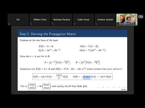
- A layer matrix uses cos δ on its diagonal and terms proportional to −j sin δ times Y or 1/Y off the diagonal.
- For a stack, multiply the layer matrices from right to left to relate the fields at the front and back interfaces.
- The electric field is written as forward and backward waves, with amplitudes A and B in the slab and reflection and transmission coefficients R and T outside it.
- The magnetic field uses the layer admittance, with opposite signs for forward- and backward-propagating components.
- Continuity of tangential electric and magnetic fields at z = 0 and z = d gives two equations that determine R and T.
- For a general stack, the total transfer matrix connects the front and back fields, enabling its overall reflection and transmission to be calculated.
- Reflectance is |R|², while transmitted power requires an admittance correction: Tpower = |T|²Y₃/Y₁.
- For a lossless slab, reflected and transmitted powers add to one: Rpower + Tpower = 1.
- When the exterior media match, the slab's reflection vanishes at phase conditions δ = mπ, producing maximum transmission.
- Reflection is strongest near δ = (m + 1/2)π, where the internally reflected waves interfere constructively.
- A MATLAB example sweeps wavelengths from 400 to 700 nm and plots reflectance, transmittance, and their sum for a BK7 glass slab.
- The plotted power balance remains R + T = 1, while selected wavelengths reach nearly complete transmission through the air-glass-air structure.
- At a fixed wavelength of 650 nm and slab thickness of 5 μm, changing the incidence angle produces strongly varying s- and p-polarized responses.
- Near grazing incidence, reflection approaches unity; p polarization also exhibits a broad low-reflection region around roughly 48° to 60°.
- Alternating titanium dioxide and silicon dioxide layers on glass form a periodic multilayer reflector.
- A multilayer example shows high reflectance across approximately 500 to 570 nm, including the 532 nm green-laser wavelength.
- An eight-pair stack is designed for a narrow transmission peak near 547.28 nm, with transmission close to one and reflection near zero.
- Increasing the number of periods sharpens the spectral features, producing higher-finesse reflection bands and narrow transmission resonances.
- For a dielectric slab, the wavelength free spectral range is approximately Δλ = λ²/(2nd cos θ), with a corresponding frequency-domain form.
- The finesse is related to interface reflectance by F ≈ π√R/(1 − R); the coefficient of finesse gives the normal-incidence transmission form 1/(1 + Fcoeff sin²δ).
- A single-layer antireflection coating ideally has index ncoat = √(n₁n₃) and quarter-wave thickness d = λ₀/(4ncoat).
- For air and glass with n₃ = 1.5, the ideal coating index is about 1.225, so practical coatings use available low-loss materials such as an index near 1.38.
- For a 1 mm glass slab with n = 1.5 at λ = 1550 nm, the free spectral range is about 0.80 nm.
- The maximum possible transmittance of the lossless slab is one; its minimum follows from the maximum reflectance at the relevant phase.
- At a single interface, p-polarized reflection vanishes at Brewster's angle, while s-polarized reflection remains nonzero.
- Above the critical angle for light traveling from a higher-index to a lower-index medium, total internal reflection has unit reflection magnitude and a phase shift.
- Under total internal reflection, the field in the lower-index medium is evanescent: it decays away from the interface rather than propagating into the medium.
- The evanescent field is concentrated within roughly a wavelength of the interface, enabling surface-sensitive methods such as TIR fluorescence microscopy.
- The lecture's animation illustrates that a target well above the interface may produce little detectable field, while features around 100 to 200 nm from it can remain observable.
- The phase behavior of complex reflection coefficients is also relevant to changing polarization, including conversion between linear and circular polarization with suitable optical elements.
- A practical refractive-index measurement uses p-polarized laser light and records the angle where reflected power reaches its minimum.
- For incidence from air, Brewster's-angle measurement estimates the sample index through n ≈ tan θB.
- A proposed setup keeps the sample, laser, and detector fixed while coordinated mirrors and polarizers adjust incidence and collection angles.
- In a surface-plasmon-resonance sensor, changing the refractive index around a silver film shifts the resonance angle, allowing particle concentration in a microfluidic channel to be inferred.
- A wedged optical sample has nonparallel interfaces, directing front- and back-surface reflections apart to reduce unwanted interference.
- Coherence gating uses a broadband source and spectrometer to distinguish returns arriving at different times from different depths.
- Waveguide attenuation can be estimated by measuring two same-material samples of lengths L₁ and L₂ and comparing their transmitted powers.
- The attenuation coefficient follows from the logarithm of the power ratio divided by L₂ − L₁, separating propagation loss from similar interface reflections.
- The lecture cites photonic-chip waveguide losses around 0.02 dB/cm and notes that a 10 μm guide therefore has extremely small propagation loss.
- A long fiber link illustrates the scale of optical communications: a Singapore-to-United States submarine route spans about 16,000 km.
- Such long-distance systems use active repeaters roughly every 40 to 50 km, with power supplied along the submarine cable.
- A reported 800 Gbps transmission demonstration underscores why attenuation, repeaters, and detector performance matter in practical links.
- Two dielectric slabs can be shifted relative to one another to vary interference and produce maximum and minimum transmission for estimating refractive index.
- Optical reflectance and transmittance correspond to RF scattering parameters such as S₁₁ and S₂₁; reciprocal lossless systems have equal forward and reverse transmission.
- Because real samples can absorb and scatter as well as reflect, an integrating sphere collects light over multiple directions for a more complete energy measurement.
- Etalon components use dielectric films and coatings to engineer reflection or transmission over selected wavelengths.
- Detector signal-to-noise ratio and bandwidth set limits on the weakest optical signals that can be measured, especially in long-waveguide experiments.
- Stable sources, clean mirrors and beam splitters, and careful handling of optical surfaces improve measurement repeatability.
- Transfer-matrix calculations can be explored in MATLAB or Python to model slabs and multilayer structures across wavelength and angle.
- The next lecture topic is optical fibers, including ray-optics approximations, the V-number, and graded-index fibers' effect on dispersion.
Transcript excerpt
0:04 Good. All right, so let's start guys. I hope you guys can see my screen number two, which is today's subject, like, slap, how aetraumatic waves are reflected back from a diatrics lab and how they are transmitted through. So like in the beginning, you know, let's give us the formal definition of like a slap. It's basically a thin directory and in this chapter again like people assume there is NO loss, we are only dealing with direct materials. So the 1st medium has a reflective index of N one, the last medium has a reflective index of like N three and our dietrics lab has a reflective index of N two. But in free space optics, e.g., when we are in the lab, when we have this tin film. Yeah, Background is old air. So the 1st layer and the 3rd layer, they are both air meaning that, you know, the reflective index is the same. It could be a public incidents it could be you know normal incidents. So data one is the angle of incident light and we can use snails law to find data two. So data two is the direction of propagation in the direct slab.
1:26 So here there is one very important concept which is called like single pass phase. So what happens is that light will travel through the, you know, second layer, right? But for us, the important thing is like wave number along the Z. Okay, so that's why we should spend pay attention to the wave number one to Z direction, and it is basically aK0 times N two, right? That is the total wave number, but since we have this directional propagation of data two, so we have to multiply it with data two so that we will get the Z component only.
This is the start of the transcript. Save this video free for the whole transcript, searchable and time-coded.
Related notes
Summary, takeaways, and chapters were generated by AI from the video's transcript and may contain errors. The video belongs to its creator, Ergun Simsek.