EECS 373 - Fall 2026 - Lecture 12: "Serial Buses: I2C and SPI"
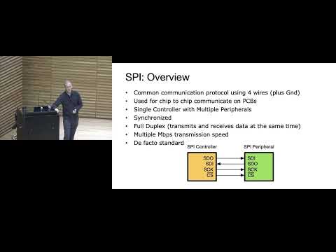 Watch on YouTube →
Overview
The lecture compares SPI and I2C as chip-to-chip serial buses, explaining their wiring, timing, addressing, electrical behavior, and tradeoffs. SPI uses controller-driven clocks, separate data lines, and per-device chip selects for fast full-duplex transfers; I2C shares two open-drain lines among addressed devices, using pull-up resistors, acknowledgements, and arbitration. The lecture also reviews UART and ends with a one-wire interface exercise combining serial data, addressing, and power delivery.
Key takeaways
- SPI exchanges data through controller and peripheral shift registers on clock edges, enabling full-duplex transfers; its practical speed depends on the peripheral's limits and the electrical characteristics of the bus.
- SPI scales device count by sharing data and clock lines but requires an additional active-low chip-select connection for each peripheral.
- I2C's open-drain signaling lets multiple devices safely share SDA and SCL: devices pull lines low, and external pull-ups establish high levels.
- I2C bus speed depends on the pull-up resistance and total parasitic capacitance; stronger pull-ups improve rise time but increase current and power consumption.
- An I2C ACK is low on the ninth clock: a target ACKs an address or written byte, while a controller ACKs read data to request another byte and NACKs to end the read.
- A one-wire interface can combine pre-agreed timing, device addressing, and shared-line signaling; a capacitor can harvest power from the line, but the approach is slow.
Chapters
- Homework 5 is due that night, team registration is due Wednesday, and the course will move to project work after Homework 6 and 7.
- SPI, or Serial Peripheral Interface, is commonly used for high-data-rate peripherals such as LCDs that need frequent pixel updates.
- Unlike UART's one-to-one asynchronous link, SPI supports one controller and multiple peripherals sharing bus wires.
- SPI uses controller-out and peripheral-in data, controller-in and peripheral-out data, a controller-driven clock, and a chip-select line for each peripheral.
- The controller selects a peripheral by pulling its chip-select low; unselected devices ignore the shared clock and data activity.
- A peripheral cannot initiate a transfer because the controller supplies every clock pulse.
- A useful model is a controller shift register exchanging bits with a peripheral shift register on each clock edge.
- SPI is inherently full duplex: each transmitted bit can simultaneously shift a bit back to the sender, even if a transaction uses the return data later.
- Transfers are commonly 8 bits, though device and controller packet sizes may range from roughly 4 to 16 bits; SPI itself provides no acknowledgement or flow control.
- Clock polarity, CPOL, selects the clock's idle level; clock phase, CPHA, selects whether data is sampled on the first or second clock edge.
- The CPOL and CPHA combinations produce four SPI modes, so the controller's configuration must match the peripheral's timing.
- Data is sampled when valid and toggles on the opposite edge; manufacturers' differing conventions make checking the device datasheet important.
- SPI has no single universal maximum rate; practical speed depends on the controller, peripheral datasheet, wiring capacitance, and signal integrity.
- The controller selects the clock rate to suit the peripheral; the lecture notes that some LCDs rated near 10 Mbit/s may work when overclocked to 30 or 40 Mbit/s.
- Because a peripheral cannot start SPI traffic, a separate interrupt pin can wake a sleeping controller, as in a smartwatch gyro that detects a wrist raise.
- Daisy-chaining shift-register peripherals lets data pass through multiple devices without a separate chip-select for each one; LED strips can latch shifted color values after a pause.
- Infineon's XMC 4700 has six configurable USIC channels that can support protocols such as UART, SPI, and I2C, along with FIFO buffers and interrupts.
- Dual SPI and Quad SPI send data over two or four data lanes, respectively, to increase throughput for devices such as external flash.
- SPI shares clock and data wires across peripherals but uses one chip-select GPIO per device; it avoids address bytes and supports faster transfers than asynchronous UART.
- I2C means Inter-Integrated Circuit and was developed by Philips in the 1980s to connect ICs in television sets with fewer pins.
- I2C is widely used for lower-data-rate peripherals such as temperature sensors and accelerometers; NXP maintains the protocol specification.
- The bus shares serial data, SDA, and serial clock, SCL, among devices, with controller and peripheral communication using the same data line.
- A typical I2C device uses a 7-bit address, allowing up to 128 address values; 10-bit addressing is also available, and address zero is used for broadcast.
- Unlike SPI chip-select wiring, I2C identifies a target by transmitting its address over the shared SDA line.
- External pull-up resistors establish logic high; their resistance and the bus's parasitic capacitance determine how quickly the lines rise and thus constrain speed.
- I2C devices use open-drain outputs: an NMOS transistor can pull a line low, while an external resistor pulls it high.
- Because devices do not actively drive the line high, a controller and peripheral can share SDA without the destructive high-versus-low output conflict possible with push-pull signaling.
- The bus participant must read the shared pin as well as drive it, allowing it to detect the actual line value.
- A Falstad simulation shows that bus wires and device pins add parasitic capacitance, producing curved rising edges as pull-up resistors charge the bus.
- Higher resistance or more attached devices can make SDA or SCL rise too slowly; reducing resistance improves rise time but increases current and power use.
- An I2C target can use clock stretching by holding SCL low when it needs more time before the controller continues.
- I2C data is valid while SCL is high; devices change SDA while SCL is low, leaving time for the slower resistor-driven rising edge.
- A transaction starts when the controller pulls SDA low while SCL is high, then begins clocking the bus.
- A stop condition returns SDA high while SCL is high, leaving both bus lines idle high.
- A typical I2C frame begins with a start condition, followed by a 7-bit address and a read/write bit.
- The addressed target acknowledges by pulling SDA low on the ninth clock; a high level indicates no acknowledgement.
- A missing ACK can indicate incorrect wiring, an incorrect device address, or an absent target; a logic analyzer can reveal the address and ACK state.
- I2C can support multiple controllers through wired-AND behavior: a low from any device makes the shared line low.
- Controllers monitor the bus while transmitting; a controller that sends a one but reads a zero loses arbitration, favoring the message with the earlier dominant zero.
- During reads, the controller ACKs to request more data and NACKs to finish; during writes, the target ACK indicates it accepted the byte.
- A logic analyzer decodes protocol events, while an oscilloscope helps diagnose analog problems such as slow, curved rising edges.
- The XMC 4700's configurable USIC channels support I2C controller or target operation, including multi-controller arbitration.
- The XMC can route I2C clock input and output to separate pins, though those pins must be connected externally for the usual shared-clock arrangement.
- I2C needs only SDA and SCL plus power and ground, but pull-up sizing creates a speed-versus-power tradeoff and address bytes add overhead to each transaction.
- Unlike SPI, I2C does not require a chip-select wire per device, but devices on the same bus need distinct addresses.
- UART uses TX and RX without a clock and requires both endpoints to agree on a baud rate; GPS receivers are a common continuous-streaming example.
- SPI uses separate transmit and receive lines plus a controller clock, and adds a chip-select wire for each peripheral.
- I2C shares two open-drain signal lines, uses device addresses and acknowledgements, and relies on pull-ups for logic-high levels.
- The review contrasts UART's asynchronous streaming, SPI's fast shift-register transfers, and I2C's compact multi-device wiring.
- The class challenge asks how to communicate with multiple devices using one signal wire, leading to ideas such as turn-taking and device addresses.
- The proposed interface combines UART-style pre-agreed timing with I2C-style shared-line communication and addressing.
- A pull-up resistor can supply voltage on the data line, while a capacitor stores energy during brief low periods to power a remote sensor.
- Combining data and power on one wire can reduce cabling, though the resulting interface is comparatively slow.
Transcript excerpt
0:21 All right. You guys hear me? Okay. >> Yeah. Good. Good. All right. Cool. All right. So, Professor Sample is out this week. So, I'm your substitute teacher. I was thinking maybe we just watch a movie if that's okay. All right. Uh, so we're going to be learning about spy today. Um, couple announcements. So, homework 5 is due tonight. Um, team registration, if you haven't done that already, I think a lot of you haven't done it. Um, just fill out that Google form with your teammates. uh do that by Wednesday. If you don't have a team already, please reach out to me or Professor Sample and we'll help you get on a team. Uh we don't want any stragglers. So maybe you
1:10 can also come to me after the lecture and we can try and find everyone a team. Okay. Um after tonight, you have homework six and homework 7. Um and then after that, you're all done with homework and we'll go into the project phase and all your focus will be on that. So uh last week you talked about uh UART that was a serial interface. We are going to be talking about SPI. Today stands for serial peripheral interface. Um it's kind of the same idea where we're we're having some chips on a board talking to each other. Uh but they've implemented it slightly differently. So if you want to do some reading on how Spy works, you can go to the reference manual. For whatever reason, Infinine
1:57 has decided to change the name of it. So, they call it synchronous serial channel in the manual. Um, they kind of do that with all of them. For some reason, they changed the name. Um, you can also go to that that ARM book that
This is the start of the transcript. Save this video free for the whole transcript, searchable and time-coded.
Related notes
Summary, takeaways, and chapters were generated by AI from the video's transcript and may contain errors. The video belongs to its creator, Interactive Sensing and Computing Lab.