EECS 373 - Fall 2026 - Lecture 11: "Serial Bus Over & UART"
 Watch on YouTube →
Overview
The lecture frames serial-protocol selection around speed, wiring, distance, clocking, and device count, then explains UART as a simple asynchronous link for communication between two devices. It covers UART signaling and framing, receiver oversampling, baud-rate agreement, parity-based error detection, decoding a 9600-baud example, and how microcontrollers bridge serial data to parallel processing, USB, and radio modules.
Key takeaways
- UART receivers recover timing by detecting the falling-edge start bit and counting with an internal clock commonly running 8×, 16×, or 32× faster than the agreed baud rate.
- A standard 8N1 UART frame uses 10 transmitted symbols for 8 payload bits, so its useful data rate is lower than its baud rate.
- UART transmit and receive lines cross between devices—TX connects to the other device’s RX—and a shared ground is required for voltage reference and current return.
- UART framing is flexible but must be configured consistently at both ends: baud rate, data width, parity, stop bits, and bit order.
- Microcontroller UART peripherals bridge serial communication and processor-friendly parallel data using shift registers, FIFOs, and interrupts; failing to drain a receive FIFO can overwrite incoming data.
- UART remains useful in embedded systems as a simple interface to USB bridge chips and wireless modules that handle more complex external protocols.
Chapters
0:00
Course Logistics and Serial-Protocol Lecture Setup
- Slide ideation work is due Thursday, team formation is Friday, and homework is due Monday.
- The lecture reviews communication-protocol design choices before focusing on UART and possibly beginning SPI.
2:04
Protocol Selection: Wiring, Speed, Clocking, and Arbitration
- Parallel buses send multiple bits per clock cycle but are generally suited to short distances; serial links reduce wiring and pin requirements.
- Protocol selection also depends on synchronous versus asynchronous timing, the number of sources and destinations, and arbitration methods such as addresses or select lines.
- Data formats and redundancy sit above the signaling layer, which defines how physical lines change.
6:31
Why ARM APB Uses Parallel Buses On-Chip
- The Advanced Peripheral Bus (APB) uses parallel signaling internally to transfer data faster than sending each bit over successive serial clock cycles.
- On-chip wiring and space are less restrictive than external pins, while chip pads or bumps are limited and costly.
- Serial communication is therefore a practical choice for off-device links, while parallel buses suit high-speed transfers between components on a chip.
10:52
UART’s History and Continued Use in Embedded Systems
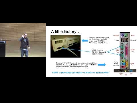
- UART means Universal Asynchronous Receiver/Transmitter and is an established, clockless signaling method dating to the early era of computer serial ports.
- RS-232, RS-422, and RS-485 use related serial framing concepts but differ in electrical signaling, including voltage levels and single-ended versus differential transmission.
- UART persists in embedded systems because its hardware is simple, inexpensive, widely supported, and familiar to engineers.
16:49
UART TX/RX Wiring, Electrical Levels, and Ground
- Connect one device’s TX to the other device’s RX, and vice versa; UART’s transmit and receive labels are relative to each device.
- UART links require a shared ground to establish a voltage reference and provide a return path for current.
- RS-232 can use approximately ±12 V and invert the signal relative to common 0–5 V UART signaling, so a compatible level converter may be necessary.
21:01
How UART Receivers Recover Timing Without a Shared Clock
- UART receivers detect the falling edge from the idle-high line as the start of a frame, then use a faster internal clock to estimate bit-center sampling times.
- Common oversampling factors include 8×, 16×, or 32× the baud rate; the transmitter and receiver agree on the rate in advance.
- Independent clocks drift relative to one another, so the start bit re-synchronizes the receiver for each short frame rather than relying on indefinite synchronization.
28:01
Baud Generators and Configuring UART Timing
- A UART peripheral’s baud-rate generator divides the device clock to produce the configured serial timing.
- Receiver logic uses the faster internal clock for oversampling, while the devices’ shared agreement is about the line’s baud rate—not their internal clock frequencies.
- Serial terminal programs and device data sheets specify supported rates; 9600 baud is a common default.
33:54
UART Frame Structure: Start, Data, Parity, and Stop
- A typical frame begins with a low start bit after the line has been idle high, followed by data bits and one or two stop bits.
- Eight data bits with no parity and one stop bit is commonly written as 8N1; UART configurations can also use different data widths and optional parity.
- Transmitter and receiver must agree on baud rate, data-bit count, parity, stop-bit count, and bit order; LSB-first is common.
41:41
Baud Rate Versus Useful Data Rate
- Baud rate measures symbols transmitted per second, whereas useful data rate counts only payload bits.
- Start, parity, and stop bits add framing overhead, so an 8N1 frame sends 10 symbols for every 8 data bits.
- In other signaling systems, a symbol can encode multiple bits; UART’s ordinary binary signaling carries one bit per symbol.
44:12
Reading UART Waveforms and Practicing Frame Decoding
- To decode an oscilloscope trace, identify the idle-high interval and falling-edge start bit before sampling each data bit at its expected center.
- The example uses an eight-bit, no-parity, one-stop-bit frame and requires knowing that bits are sent LSB-first.
- The in-class exercise emphasizes labeling start and stop bits as framing rather than treating them as payload values.
58:04
Decoding ASCII Data and Measuring a 9600-Baud Signal
- The worked waveform decodes to the ASCII character G after identifying the start bit, reading data LSB-first, and checking the stop bit.
- A provided ASCII table can translate the recovered binary value into a character.
- Baud rate can be estimated from the time interval spanning a known number of bit periods; the class example yields approximately 9600 baud.
1:03:27
UART Shift Registers, FIFOs, and Interrupt Handling
- A UART shift register converts incoming serial bits into a parallel word so the processor can read a complete value rather than sample every bit itself.
- FIFO buffers absorb bursts of data, but software must drain the receive buffer before new data overwrites unread entries.
- Interrupts can notify the processor when data arrives, an error occurs, or a transmit buffer is ready for more data.
1:06:29
UART Bridges to USB and Wireless Modules
- A USB-to-UART bridge chip handles the more complex USB signaling and presents a simpler serial interface to the microcontroller.
- Development boards commonly use such a bridge so a computer can exchange UART data over a USB cable.
- Bluetooth, XBee, or Zigbee modules can similarly accept UART configuration and data while managing radio synchronization and transmission themselves.
1:10:37
Reconfigurable Serial Interfaces in Microcontrollers
- A microcontroller’s serial interface channels can often be configured for UART, SPI, I²C, I²S, or other protocols.
- The lecture describes up to six channels, with buffers and configurable interrupts for events such as available data, completed transmission, or errors.
- Peripheral and pin assignments determine which protocols can run simultaneously on an embedded system.
1:12:23
UART Trade-Offs and Practical Limits
- UART uses two signal wires plus shared ground and needs no shared clock, making it convenient for a direct two-device connection.
- Common UART hardware supports up to nine data bits, though eight-bit data is standard; parity can detect some transmission errors but cannot correct them.
- The devices must pre-agree on framing, bit order, and baud rate, and timing accuracy is limited by clock and divider error.
Summary, takeaways, and chapters were generated by AI from the video's transcript and may contain errors. The video belongs to its creator, Interactive Sensing and Computing Lab.