EECS 373 - Fall 2026 - Lecture 9: "Timers: Capture & Compare"
 Watch on YouTube →
Overview
The lecture builds a practical model of capture-and-compare timers, from crystal-derived clocks and prescalers to counters, period registers, input capture, and compare outputs. It applies that model to measuring event intervals and generating pulse-width modulation (PWM), emphasizing how prescaler and counter choices trade measurement range against resolution and how compare values control LED brightness and motor signals.
Key takeaways
- A timer’s prescaler sets the tick duration, while its period register sets how many ticks form a repeating cycle; together they determine the waveform period.
- Input capture timestamps external edges in hardware by copying the current count into a register, enabling interval measurement without relying on precise CPU response timing.
- With a 16-bit counter, a slower tick extends the maximum measurable interval but reduces timing resolution, so prescaler selection must account for both the shortest and longest expected events.
- Compare hardware triggers output changes when the counter reaches a programmed value; keeping the period fixed while adjusting the compare value changes PWM duty cycle.
- For an up-counting timer that starts at zero, the cycle length is (PR + 1) timer ticks, an off-by-one detail important when calculating timing and PWM settings.
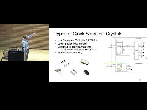
- A 32.768 kHz crystal is useful for human-scale timekeeping because 2^15 clock ticks equal one second.
Chapters
0:00
Course Deadlines, Ideation Slides, and Project Team Formation
- Homework 4 is due Monday; individual project ideation slides are due the following Thursday.
- The ideation assignment calls for three slides, an image, and fewer than 100 words; a star marks a project the student would like to present.
- Teams register the following Tuesday, then submit a proposal and meet with the instructor or James for feasibility feedback.
2:37
Why Embedded Systems Use Timers to Control the Physical World
- Microcontrollers are effective at controlling timing even when they cannot directly manipulate analog quantities.
- Servo position can be encoded by pulse timing, while DC motor speed and LED brightness can be controlled with PWM.
- A timer converts a clock into repeatable intervals for measuring elapsed time or scheduling hardware actions.
8:49
Quartz Crystals and the Clock Sources Behind a Timer
- Quartz crystals use piezoelectric behavior and physical vibration to provide a repeatable timing reference.
- Low-frequency crystals commonly operate around 10–100 kHz; 32.768 kHz is a standard value used for human-scale timekeeping.
- Higher-frequency ceramic or surface-acoustic-wave resonators commonly operate around 10–100 MHz, and the XMC 4770 has external crystal inputs.
12:06
Clock Scaling with Internal Oscillators and Phase-Locked Loops
- Some microcontrollers use digitally controlled oscillators to trade processing speed for lower power, though this device relies on fixed clock sources.
- A phase-locked loop (PLL) can multiply a 16 MHz reference to produce a 144 MHz clock by comparing divided output edges with the reference.
- PLL-generated clocks bring trade-offs including increased power and jitter; clock trees route and divide frequencies for cores, buses, and peripherals.
17:28
Timer Anatomy: Prescaler, Counter, and Period Register
- A timer receives a clock, uses a prescaler to slow it down, and advances a counter on each resulting tick.
- The counter can be read, written, and configured to count up or down; the device’s timer counters are generally 16-bit.
- A period or reload register can end a count cycle before natural counter overflow and reset or reload the counter.
22:18
Clock Dividers and the Prescaler Naming Trap
- A chain of flip-flops can divide a clock by 2, 4, 8, and other power-of-two factors, with a mux selecting a divided output.
- A general prescaler may support division factors beyond powers of two, but Infineon documentation uses “prescaler” for a clock-divider structure.
- The naming difference matters when reading datasheets: check the available division values rather than assuming a term has one universal meaning.
26:06
Counter Behavior: Counting, Loading, and Resetting
- A counter’s essential operations are counting up or down, holding its value, and loading a new value.
- JTAG debugging can inspect register state through hardware scan paths that shift data through flip-flops.
- The lecture focuses on what the counter module does rather than requiring students to derive its internal flip-flop topology.
29:09
Using the Period Register to Generate a One-Second Tick
- Timer counts advance in discrete clock ticks, even when timing diagrams draw the count as a continuous ramp.
- With a 32.768 kHz clock, the 32,768 ticks in 2^15 correspond to one second, making this crystal frequency convenient for timekeeping.
- Hardware can reset or reload the counter when it reaches the period value without involving the CPU; software may separately enable an interrupt.
34:44
Up, Down, and Center-Aligned Timer Counting
- Timers may count upward, count downward, or count up and then down before repeating.
- Up/down counting supports waveform generation and can extend the useful timing range.
- For center-aligned counting, endpoints are not counted twice; the example from 0 to 6 and back avoids double-counting 0 and 6.
36:08
Input Capture: Timestamping External Events
- An input-capture unit copies the current timer count into a capture register when an external event, such as a rising edge on a GPIO, occurs.
- Capturing successive edges lets hardware record the interval between events, as in measuring the rotation rate of a wind-speed sensor.
- To configure a 16-bit timer, choose a prescaler that prevents overflow over the longest expected interval while retaining enough ticks to distinguish the shortest interval.
44:23
Compare Events and PWM for LEDs and Motors
- A compare unit triggers an output action when the counter equals a programmed compare value; unlike capture, it does not require an external event.
- The period register sets the repeating cycle, while the compare register independently controls the pulse width within that cycle.
- PWM dims LEDs by changing duty cycle and controls motor behavior; sufficiently fast switching, around 1 kHz in the example, appears steady to people.
50:00
Compare Output Modes and Timer Period Calculations
- A timer output can be configured to go high or low when the count matches the compare register, with the selected mode affecting duty-cycle interpretation.
- For an up-counting timer, the waveform period is (PR + 1) times the timer clock period because counting starts at zero.
- Changing the compare value alters the high-time fraction without changing the timer’s overall period.
55:00
Worksheet: Configure a 16 MHz Timer for 10 ms PWM
- The worksheet asks students to produce a 10% duty-cycle waveform with a 10 ms period from a 16 MHz timer clock.
- Students first select a prescaler and period-register value that fit the 10 ms cycle within a 16-bit counter.
- They then calculate the compare-register value for a 1 ms high interval; the transcript ends before a complete worked answer is given.
Summary, takeaways, and chapters were generated by AI from the video's transcript and may contain errors. The video belongs to its creator, Interactive Sensing and Computing Lab.