EECS 373 - Fall 2026 - Lecture 10: "Timers Resolution vs Length & Serial Bus Overview ”
 Watch on YouTube →
Overview
The lecture explains how timer prescalers, counter width, and period and compare registers determine both measurable duration and timing resolution, then applies those trade-offs to PWM, ARM SysTick, and a laser-pulse design example. It introduces off-chip serial communication by comparing parallel and serial wiring, synchronous and asynchronous timing, error checks, flow control, bus topologies, and common protocols including UART, SPI, and I²C.
Key takeaways
- Timer prescaling creates a direct range–resolution trade-off: a larger divide factor lets a fixed-width counter run longer before overflow but increases the smallest measurable time step.
- PWM period and pulse width are controlled independently through timer period and compare values; shadow registers prevent mid-cycle updates from creating malformed or duplicate pulses.
- A 16-bit timer cannot directly cover every desired interval at fine resolution; software virtual counters or concatenated wider counters extend duration, but interrupt-based timing is less deterministic.
- SysTick is ARM’s standardized 24-bit core timer for common timing and scheduling needs, while peripheral timers handle device-specific functions such as PWM and event capture.
- Serial links reduce pin and wiring requirements compared with parallel buses and can handle long distances more robustly, while parallel links provide multiple bits per clock for high-bandwidth local connections.
- UART, SPI, and I²C illustrate different serial design choices: asynchronous timing without a clock wire versus clocked communication, alongside different approaches to device selection and coordination.
Chapters
0:00
Project Slides, Team Formation, and EECS 373 Deadlines
- Homework 4 is due on lecture day, with office hours scheduled afterward.
- Students must submit ideation slides by Thursday in both Gradescope and a class-visible Google Slides folder.
- The Friday team-formation event is planned for 4:30–6:30; teams should generally have three or four members, with five allowed if needed.
- The project guideline suggests roughly one more feature than the number of team members; students who lack teammates by Monday should contact the course staff.
5:24
Timer Basics: Prescalers, Counters, and Period Registers
- A timer receives a source clock and uses a prescaler—typically a divide-by-2^n setting on the class hardware—to reduce its frequency.
- The counter advances on incoming clock edges; a 16-bit counter can count up to its limit before overflowing.
- A period register sets the counter’s reset point, while reaching that point can produce an interrupt, a signal for another timer, or another hardware event.
- The prescaler slows the timer clock rather than increasing it, trading finer timing increments for longer counting intervals.
11:52
Timer Resolution Versus Maximum Duration
- Resolution is the smallest interval a timer can distinguish; with a prescaler of 2, the smallest step is two source-clock ticks.
- Increasing the prescaler extends the maximum countable duration before overflow but makes each measurable step coarser.
- Reducing the prescaler improves resolution but shortens the duration a fixed-width counter can cover.
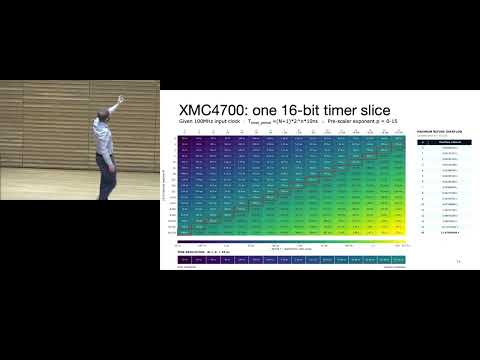
- For a 100 MHz input, the lecture’s table compares prescaler settings with both maximum timer duration and minimum time step.
20:24
Choosing Timer Settings and Extending Time with Virtual Counters
- Different prescaler and counter settings can produce duplicate timer durations, giving a choice between finer resolution and a longer range.
- A software virtual counter can extend time by accumulating hardware timer interrupts and tracking larger deadlines.
- Interrupt-based timekeeping adds entry and exit latency, and interrupt timing is not deterministic enough for very precise measurements.
- Virtual timers are better suited to human-scale intervals such as roughly 100 milliseconds, minutes, or hours; wider or concatenated hardware counters are another option.
25:36
Capture Timers, Compare Events, and PWM Generation
- A capture timer records elapsed time between external events, much like a stopwatch.
- A compare timer triggers an event when its counter reaches a programmed compare-register value.
- PWM uses timer period and compare values to set a waveform’s repetition rate and pulse width; changing the compare value changes duty cycle.
- PWM can control devices such as dimmable LEDs, servos, and DC motors, and timer capture can measure pulse widths from sensors.
28:41
Shadow Registers Prevent PWM Glitches
- Writing a live PWM compare value mid-period can create an unexpectedly short pulse or multiple pulses within one period.
- Shadow registers stage new period and compare values before transferring them to the active registers.
- Software requests a synchronized update so the hardware applies staged values at a valid point, often when the timer period reloads.
- The synchronization is about preserving the PWM cycle boundary, not merely aligning a write to a source-clock edge.
37:19
ARM SysTick, Watchdogs, and Portable Timing
- ARM defines a 24-bit SysTick timer as a common processor-level feature, distinct from manufacturer-specific peripheral timers.
- SysTick can provide a standard timing base for software across ARM-based microcontrollers, supporting portability and operating-system scheduling.
- A watchdog timer can reset a system if software fails to periodically refresh it, helping recover from hangs such as a stuck loop.
- Peripheral timers serve device-specific timing needs, while SysTick is intended as a core-level timebase.
43:02
Super Loops, Interrupts, and Real-Time Operating Systems
- A super loop initializes hardware and repeatedly runs short tasks such as reading a temperature sensor, updating a display, and checking buttons.
- Super-loop tasks should be short and predictable; interrupt handlers should generally do limited work, such as storing ADC data or setting a flag.
- A real-time operating system schedules tasks with different priorities and uses timer ticks to decide which task runs.
- A timer can make a main loop run at a fixed interval, such as every 50 milliseconds, rather than whenever variable-duration work happens to finish.
46:37
SysTick Reload, Countdown, and Calibration Registers
- SysTick counts down from a programmable reload value and can generate an interrupt when it reaches its terminal count.
- Its basic register set includes control and status bits, a reload value, a current count, and a calibration value.
- Some implementations offer a divide-by-8 clock option; the available control is simpler than the more configurable peripheral timers.
- The calibration register helps software target a known delay across processors with different clock speeds, with examples around 50 or 100 milliseconds.
49:25
Worked PWM Design: 100 MHz Clock and a 200 Hz Laser Pulse
- The design example starts with a 100 MHz timer clock, a 16-bit counter, and a requested 200 Hz pulse repetition rate, corresponding to a 5 ms period.
- The pulse width must be adjustable between 10 and 100 microseconds, so prescaler selection must satisfy both the full-period range and the required timing resolution.
- After selecting a prescaler, the period-register value is calculated from the 5 ms period and timer tick; the count uses N−1 because the counter includes zero.
- Compare-register values are calculated from the desired pulse widths and timer tick, allowing pulse width—and therefore delivered power—to be adjusted.
1:03:51
Off-Chip Communication: Bus Design Questions
- Serial-bus topics concern communication between devices on a PCB, unlike the Advanced Peripheral Bus, which connects modules within a chip.
- Bus design involves wiring type, speed, synchronous or asynchronous timing, and whether communication is point-to-point or supports multiple devices.
- Protocol decisions include bit order, packet headers, addresses, and error-detection fields such as checksums or CRCs.
- Arbitration determines which device may transmit, using approaches such as a designated controller or distributed access.
1:06:38
Parallel Versus Serial: Bandwidth, Pins, and Distance
- Parallel buses transmit multiple bits per clock cycle and are used where high bandwidth justifies more pins and wiring, with examples including PCI Express and CompactFlash.
- Pin count is a physical bottleneck: chip packaging and connections limit how much data can enter or leave a device.
- Serial links send bits over fewer data wires, reducing connections and often working better over longer distances.
- Long parallel links face skew because separate lines can have different propagation delays; serial links avoid coordinating arrival times across a wide group of data bits.
1:08:35
Serial Error Detection and Synchronous Versus Asynchronous Timing
- USB uses differential data lines, D+ and D−, carrying complementary versions of the signal so the receiver can detect data more robustly in noise.
- A parity bit can provide a simple error check by encoding whether the data bits have even or odd parity; CRCs offer another packet-level checking method.
- Synchronous protocols send a clock signal so the receiver knows when to sample data; asynchronous UART omits the clock wire and recovers timing from the start bit.
- Removing the clock wire saves connections but requires more receiver timing work, and asynchronous communication is generally less suited to the highest speeds.
1:15:29
Flow Control, Bus Topologies, Arbitration, and Common Protocols
- Flow control and handshaking coordinate when devices may send or receive; the APB’s PREADY and PENABLE signals illustrate explicit coordination.
- Common arrangements include point-to-point links and shared bus or star topologies; rings and mesh networks are other options.
- A device can be selected through a dedicated select line or addressed through packet or protocol fields, with arbitration deciding who communicates.
- UART, SPI, and I²C are identified as widely used serial protocols; the lecture also mentions Ethernet and the possibility of covering CAN.
Summary, takeaways, and chapters were generated by AI from the video's transcript and may contain errors. The video belongs to its creator, Interactive Sensing and Computing Lab.