EE 330 Lecture 2026/9/17 Ch4 #2
Overview
The lecture moves from ideal-diode circuit analysis to real-diode behavior and practical approximations. It uses diode-state checks and waveform examples, introduces the exponential I-V relation with a thermal voltage of 25 mV, and compares ideal, constant-voltage, and real or SPICE models, including a graphical load-line method and a junction-area example.
Key takeaways
- Ideal-diode analysis is a state-checking method: assume on or off, solve the circuit, and reject any state that implies an impossible diode voltage or current.
- At approximately 25°C, the lecture uses a thermal voltage of 25 mV in the real-diode exponential relation, explaining why small changes near 0.7 V can produce large current changes.
- A 10-to-1 junction-area ratio is modeled as a 10-to-1 saturation-current ratio, which can be combined with Kirchhoff's current law to solve diode-current sharing.
- The intersection of the resistor load line and the diode I-V curve determines the operating point when the exponential diode equation is difficult to solve directly.
- For quick silicon-diode circuit estimates, the 0.7 V constant-voltage model gives 1.3 mA through a 1 kΩ resistor from a 2 V source, while a 0.2 V source leaves the diode off.
Chapters
- For an ideal diode, begin by assuming each diode is on or off, then verify that the resulting voltages and currents support those assumptions.
- Use the model specified in a problem: ideal-diode analysis is not a substitute for a real-diode or SPICE model when those are requested.
- The lecture begins by finishing several ideal-diode examples before introducing real-diode behavior.
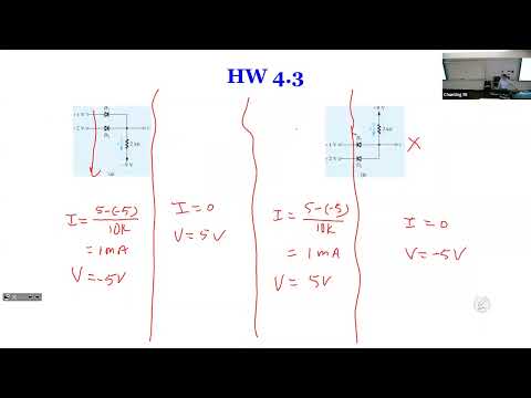
- In a network with three ideal diodes and different voltage sources, assume a diode conducts and check whether its implied node voltage makes the other diode states consistent.
- The conducting diode clamps the shared node to its source voltage; incompatible diodes must be off because an ideal diode cannot support a voltage drop.
- The order of testing diodes does not matter, but some starting assumptions may require more steps to reject.
- For a circuit with 5 V at the top and 1 V, 2 V, and 3 V reference branches, the consistent ideal-diode state clamps the node to 1 V and leaves the higher-reference diodes off.
- A diode that is off carries zero current, so a resistor with zero current has no voltage drop and its node remains at the connected source voltage.
- With two reference diodes, test all four possible on/off combinations; incompatible clamp voltages rule out simultaneous conduction.
- A 1 kHz input sine wave has a period of 1 ms; a single ideal diode passes one polarity and blocks the other.
- Two ideal diodes in series in the same direction act like one in this analysis because each has a zero-volt on-state drop.
- Opposed diodes in series block current in both polarities, while oppositely oriented parallel diodes conduct on alternate half-cycles and preserve the full sine-wave output.
- Unlike an ideal diode, a real diode can be driven by a voltage source, but its current rises sharply as forward voltage approaches the conducting region.
- The Shockley relation is approximately I_D = I_S(e^(V_D/V_T) - 1), where I_S is saturation current and V_T is the thermal voltage.
- At about 25°C, the lecture uses V_T = 25 mV; near 0.7 V, a small voltage increase can produce a large current increase.
- A real reverse-biased diode has a small leakage current, often negligible for ordinary circuit calculations.
- If reverse voltage exceeds the diode's breakdown threshold, current can rise sharply and heat can destroy the device.
- Zener diodes are specifically designed to operate in the breakdown region, unlike ordinary diodes.
- The lecture describes forward current as nearly zero below roughly 0.5 V and rapidly increasing as the diode approaches about 0.7 V.
- Above the knee, the diode voltage alone does not determine current; external circuit elements such as resistors limit it.
- Using the exponential law, current at two forward voltages can be related by a ratio, eliminating the unknown saturation current.
- A diode with 10 times the junction area of another has a correspondingly larger saturation current in the lecture's model.
- For the example with 10 mA entering a node and 3 mA leaving through a branch, Kirchhoff's current law assigns the remaining 7 mA to the other branch.
- The ideal-diode case establishes the current directions before the example is extended to real diodes with nonzero voltage drops.
- For real diodes, the example combines the Shockley equations with node-current conservation and the relation I_S1 = 10 I_S2.
- The diode voltage drops are related through the shared node voltage, giving two equations for the diode current and node voltage.
- For the target node voltage of 60 mV, the lecture's worked calculation reports a required current of about 4.76 mA.
- For a source, resistor, and diode in series, Kirchhoff's voltage law gives I_D = (V_DD - V_D)/R.
- With an ideal diode on, V_D = 0, so the current is V_DD/R; with a real diode, the resistor equation must be solved together with the exponential diode relation.
- The resulting nonlinear equation is difficult to solve directly, motivating graphical analysis.
- Plot the resistor relation and diode I-V curve on the same axes; their intersection gives the operating current and diode voltage.
- The resistor relation is linear, running between the zero-current point at V_DD and the zero-diode-voltage current V_DD/R.
- The intersection can be estimated from a graph or found more precisely with a computer.
- The piecewise-linear or constant-voltage model approximates a silicon diode's steep forward-conduction region with a fixed drop of about 0.7 V.
- In the off region, the diode is treated as an open circuit; in the on region, its voltage is held at approximately 0.7 V.
- The approximation is most useful once the diode is conducting strongly, not across the gradual 0.5 V to 0.7 V transition.
- With a 0.2 V source and a 1 kΩ resistor, the diode stays off because 0.2 V is below the model's 0.7 V threshold; current is zero and the diode supports 0.2 V.
- With a 2 V source and a 1 kΩ resistor, the diode is on with a 0.7 V drop.
- The conducting-case current is (2 V - 0.7 V)/1 kΩ = 1.3 mA.
- The ideal on-model sets V_D = 0 and leaves current to be determined by the external circuit.
- The constant-voltage on-model sets V_D ≈ 0.7 V and likewise uses the external circuit to determine current.
- The real or SPICE model uses the exponential I-V relation; in all three models, the off-state current is treated as zero and the off-state voltage depends on the surrounding circuit.
Transcript excerpt
0:10 You should join meronics club. >> There's nobody on that. >> Okay, we're going to get the class started very soon, but >> it's a problem with the with the computer. Um, there's somebody over here to help. But in the meantime, uh you guys have questions regarding the last lecture. Any difficulties in understanding the material or doing the or doing the homework, >> right? >> We just assume dials are on or off. >> If it conflicts with what we actually see, >> then we reverse our assumption. >> Yeah. Yeah, that's correct. I mean so far >> of course today we're going to get into uh practical or real world diodes that's
0:59 going to behave a little bit different. Uh so yeah as we move along we just go from simple and then to a little more complex uh devices. Uh but of course uh when you have a uh when you have a when you do a problem the problem itself it itself always specify what type of diet you're going to see. So if the problem says it's ideal diet don't go into the difficult model because it's not going to help you. uh it really says it's a a real diet or P uh P uh spice model and you have to do that because a linear model will not give you the right solution. So that's uh what we have to
1:48 uh have to do. So uh yesterday uh or Tuesday we went through a couple examples and I think today we have four more examples to go through with idea dial and then we're going to uh we're going to move on uh with some new contents. Uh it's going to take us just uh because we we already done a couple
This is the start of the transcript. Save this video free for the whole transcript, searchable and time-coded.
In this course
Related notes
Summary, takeaways, and chapters were generated by AI from the video's transcript and may contain errors. The video belongs to its creator, Wireless Power Transfer.