ECircuits-Lec6-2026
 Watch on YouTube →
Overview
The lecture develops feedback as a way to control amplifier behavior, deriving the closed-loop gains A/(1 + Aβ) for negative feedback and A/(1 - Aβ) for positive feedback. It connects feedback to practical design goals, including stabilizing gain against process, voltage, and temperature variation, trading gain for bandwidth, and changing input and output impedances, then previews op-amp circuit analysis.
Key takeaways
- For negative feedback, the closed-loop gain is A/(1 + Aβ); when A is large, it approaches 1/β and becomes less sensitive to variations in the amplifier's open-loop gain.
- Feedback polarity depends on the signs of the feed-forward and feedback gains as well as the input summing operation, so a plus or minus symbol alone is not enough to classify the loop.
- For a first-order op-amp response, reducing gain with negative feedback increases bandwidth while keeping the gain-bandwidth product approximately constant.
- Voltage-series feedback raises input impedance to Zi(1 + Aβ) and reduces output impedance by the same factor.
- Positive feedback has closed-loop gain A/(1 - Aβ); as Aβ approaches one, the system can strongly amplify small signals, a principle used in oscillator startup.
Chapters
- Labs begin September 14, so students need components and a breadboard ready to complete the prelab.
- The lecture introduces feedback before examining amplifier internal circuitry and revisiting op-amp analysis.
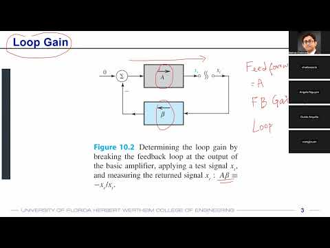
- A feedback amplifier sends a portion of its output through a network with factor β back to the input.
- Amplifier gain can vary with process, supply voltage, and temperature, or PVT, so a nominal gain may not hold across devices or conditions.
- The feed-forward amplifier has gain A, the feedback network has gain β, and their product Aβ is the loop gain, also written as T.
- Feedback can stabilize gain and alter the amplifier's input and output impedances.
- Feedback type names put the sensed output quantity first and the input mixing quantity second.
- Voltage-series feedback senses output voltage and mixes a feedback voltage in series with the input; voltage-shunt feedback senses voltage and mixes current in parallel.
- Current-series feedback converts output current into a series feedback voltage, while current-shunt feedback mixes feedback current at the input.
- The units of β depend on the signals: voltage-over-voltage for voltage-series, current-over-voltage for voltage-shunt, and impedance units for current-series.
- For voltage-series negative feedback, the amplifier input is Vi = Vs - Vf, with Vf = βVo and Vo = AVi.
- Substitution gives Vo/Vs = A/(1 + Aβ), where Aβ is the loop gain.
- With no feedback, Vi equals Vs and the overall gain is simply the feed-forward gain A.
- With positive A and β, subtracting the feedback signal produces negative feedback, while adding it produces positive feedback.
- A negative gain in either path can reverse the effective sign, so the summing-node plus or minus symbol alone does not determine feedback polarity.
- Blood-glucose regulation illustrates negative feedback: insulin responds to elevated glucose, while glucagon responds to low glucose.
- Body-temperature control also uses negative feedback, with sensing and control signals prompting sweating to counter rising temperature.
- For positive feedback, Vi = Vs + Vf and the closed-loop gain is A/(1 - Aβ).
- As Aβ approaches 1, the denominator approaches zero and the idealized closed-loop gain grows dramatically.
- Positive feedback can reinforce small signals such as noise and is used in oscillator startup, while uncontrolled reinforcement can destabilize a system.
- An op-amp's open-loop gain is high at low frequency and declines after its bandwidth, commonly specified at the minus-3 dB point.
- The frequency where gain reaches unity, or 0 dB, is the unity-gain frequency; for a first-order response, it corresponds to the gain-bandwidth product.
- Negative feedback reduces closed-loop gain by a factor related to 1 + Aβ and increases bandwidth for a first-order amplifier.
- The lecture illustrates the tradeoff with an op-amp having open-loop gain 10,000 and bandwidth 100 Hz, whose gain can be reduced to support wider-band signals such as audio up to 20 kHz.
- When open-loop gain A is large, A/(1 + Aβ) approaches 1/β because 1/A becomes negligible.
- An amplifier whose gain varies, for example, from 9,000 to 11,000 can therefore have a more stable closed-loop gain set mainly by β.
- Implementing β with resistor ratios helps reduce sensitivity to process, voltage, and temperature variation.
- For voltage-series feedback, the input impedance seen by the complete feedback circuit is Zi(1 + Aβ), greater than the amplifier's internal Zi.
- The same topology reduces output impedance by a factor of 1 + Aβ.
- The lecture uses Ohm's law and the type of quantity fed back, voltage or current, as an intuition for predicting impedance changes across feedback topologies.
- Feedback can therefore be selected to modify gain, bandwidth, and input or output impedance for a circuit's application.
- The next class revisits inverting and non-inverting op-amp amplifiers using the feedback framework.
- Both nodal analysis and feedback analysis will be applied to determine circuit behavior.
Transcript excerpt
0:00 All right, so let's get started. First off, gentle reminder that our labs are going to start on September 14th. Uh, today is September 2nd. So, I thought that I'll give a gentle reminder that make sure that you have already ordered your components. If not, please do that as soon as possible because before the September 14th lab, you need to complete your prelab, which will require those components. So if you do not have a dabboard, if you do not have the components, please make sure that uh you get a hold of them as soon as possible. All right. So in the last lecture we uh looked a little bit in terms of amplifier that okay how does the amplifier look like? What is the internal structure of the amplifier or what is the internal model of an amplifier? Not really the structure
0:47 because we are going to discuss the structure of the amplifier throughout this course but we have mostly looked into the model of the amplifier in the last lecture. So today we are also going to take a look at a important topic called feedback which is necessary to understand before we start delving into details of an amplifier or the internal circuitry of an amplifier. So we'll first look at feedback and then we'll revisit opamps a little bit and and you'll probably know most of it from your 3le 1 that uh how does opamp work what is an inverting amplifier what is a non-inverting amplifier and so on but we'll try to look at it from a fresh perspective that how do you do a DC analysis and an AC analysis right with those and then we'll gradually go into the internal circuits and the components inside the opam
1:36 all right so today what we want to
This is the start of the transcript. Save this video free for the whole transcript, searchable and time-coded.
Related notes
Summary, takeaways, and chapters were generated by AI from the video's transcript and may contain errors. The video belongs to its creator, WISE Lab - UF ECE.