ECircuits-Lec2-2026
 Watch on YouTube →
Overview
The lecture builds core circuit-analysis skills from Ohm’s law, Kirchhoff’s current and voltage laws, and ideal versus non-ideal sources through voltage and current division. It then introduces AC amplifier gain, cascaded stages, the four amplifier types, and a method for finding gain in a resistor ladder by reducing the network from the output and multiplying intermediate voltage ratios.
Key takeaways
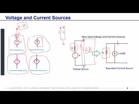
- A non-ideal voltage source is modeled with series resistance, while a non-ideal current source is modeled with parallel resistance; ideal values are 0 Ω and infinite resistance, respectively.
- In a series voltage divider, VO = VI·RB/(RA + RB), so placing the output across a much larger resistor makes it approach the input voltage.
- In a parallel current divider, the current through RB is proportional to RA, the resistance of the opposite branch: IB = II·RA/(RA + RB).
- Amplifier gain is output divided by input, which supports four types: voltage, current, transconductance, and transimpedance amplifiers.
- Cascaded stage gains multiply: three AC amplifier stages with gain 10 produce an overall gain of 1,000, while DC voltage conversion requires a DC-to-DC converter instead.
- For a resistor ladder, reduce equivalent resistances to find an intermediate divider voltage, then multiply forward divider ratios to recover the output-to-input gain.
Chapters
- Students can combine parts orders to reduce shipping costs and reuse resistor and capacitor kits they already own.
- One rotary potentiometer is needed; ordering a spare or borrowing one is suggested if it fails.
- Access arrangements for renting DAQ boards are awaiting department confirmation, expected within a day or two.
- Ohm’s law relates current to voltage and resistance: I = V/R.
- Kirchhoff’s Current Law says currents at a node sum to zero; Kirchhoff’s Voltage Law says voltages around a loop sum to zero.
- A voltage source connected to resistors without a completed loop cannot drive current, because current requires a closed path.
- Independent sources set their own voltage or current, while dependent sources are controlled by another circuit quantity, such as a voltage source producing twice another source’s voltage.
- A practical voltage source is modeled with series resistance, which causes an output drop of I·R under load; the ideal series resistance is 0 Ω.
- A practical current source is modeled with parallel resistance, which diverts current away from the load; the ideal parallel resistance is infinite.
- In these source models, parallel resistance does not change an ideal voltage source’s terminal voltage, and series resistance does not change the current from an ideal current source.
- For a source voltage VI across series resistors RA and RB, the loop current is VI/(RA + RB).
- The voltage across RB is VO = VI·RB/(RA + RB), so each resistor’s voltage drop is proportional to its resistance.
- If RB is much larger than RA, VO approaches VI; this can reduce the effect of a voltage source’s unavoidable series resistance.
- For example, a 1 MΩ output resistor paired with a 1 kΩ series resistor receives nearly the full source voltage.
- A current source feeding parallel resistors splits its current between the branches, with total current equal to IA + IB.
- The branch current through RB is IB = II·RA/(RA + RB), so it is proportional to the resistance in the opposite branch.
- A branch with infinite resistance carries approximately zero current, while the other branch receives nearly all the source current.
- This is the dual of voltage division: voltage divides across series resistors, while current divides across parallel resistors.
- Amplifiers in this course increase AC signal amplitude; they do not turn a 1.5 V DC battery into a higher DC voltage.
- DC-to-DC converters, including boost converters, can change DC voltage but are distinct from amplifiers.
- Cascaded amplifier gains multiply: three stages each with gain 10 provide total gain 10 × 10 × 10 = 1,000.
- A 1 mV-amplitude sine wave becomes 10 mV, then 100 mV, then 1,000 mV through three gain-10 stages; each stage also brings practical caveats.
- Amplifier gain is defined as output quantity divided by input quantity, and either quantity may be voltage or current.
- Voltage output over voltage input is a voltage amplifier; current output over current input is a current amplifier.
- Current output over voltage input is a transconductance amplifier, with conductance units such as siemens.
- Voltage output over current input is a transimpedance amplifier, with resistance or impedance units in ohms.
- A voltage sensor and a current sensor are different source models, so the amplifier input type must suit the sensor output.
- An op-amp’s very high input impedance means a current source may have no usable path into a basic voltage-input stage.
- Current-input signals may require a current amplifier or transimpedance amplifier; an op-amp can be configured for these functions with additional circuitry.
- The examples include small ECG signals that need amplification and crystal resonators modeled as current-generating sources.
- To find VO/VS, start at the output and simplify the network toward the input: R3 and R4 combine in series, then that combination is placed in parallel with R2.
- The reduction yields an input-side equivalent of R1 in series with the parallel combination of R2 and (R3 + R4).
- Simplifying the network hides the intermediate node voltage, so the solution restores it by working forward after finding its ratio to VS.
- Multiply the two divider ratios, Vy/VS and VO/Vy; the intermediate Vy cancels, leaving VO/VS.
- The worked resistor-ladder gain derivation concludes around 48:41, with the next class set to continue from that point.
- Brief end-of-class questions continue through the final minutes, but the transcript does not preserve enough detail to identify additional technical conclusions.
- Students are invited to take remaining questions outside because another class is scheduled afterward.
Transcript excerpt
0:01 So many of you had uh questions on the parts list. Um of course uh it is suggested that some of you can club your orders and uh send it together because in that way you can reduce the uh shipping costs. Um the other question that I saw on the group me chat is let me is is regarding all these other resistors and capacitors. So again if you have them you don't need to buy. So it just requires a very basic register/ uh capacitor kit. So if you already have them for from other classes you don't need to buy it. But in case you don't have any resistor or cap capacitor kit uh it is recommended that you buy one. Uh the rotary potentiometer probably you can order two that's the if you want
0:48 more you can you can order it because sometimes they can go bad but if you order two I don't think it will be a problem. um because you'll eventually need only one and you can share. So for example, if some of your friends are uh doing the lab on a different day and your potential meter has gone bad, you can probably borrow it for a day or two. So that should be that should be okay. Um regarding the DAG boards, of course, this is something that is very important. Um I have asked this question to the department regarding how what would be the process of uh getting the DA boards rented. So I'm still aing on that. Uh please stay tuned. But within a day or two, you should be able to have more information on how to access the dashboards. But it should be very similar to uh your other classes. So it should not be any different process.
This is the start of the transcript. Save this video free for the whole transcript, searchable and time-coded.
Related notes
Summary, takeaways, and chapters were generated by AI from the video's transcript and may contain errors. The video belongs to its creator, WISE Lab - UF ECE.