EAS4200 Aerospace Structures, Lecture 11, 2026 fall
 Watch on YouTube →
Overview
Ting Dong connects displacement-based strain definitions to tensor methods for finding principal strains and to three-dimensional linear-elastic stress-strain relations. The lecture also clarifies the quiz grading rubric, distinguishes engineering shear strain from tensor shear strain, and derives isotropic material relations using Young’s modulus, Poisson’s ratio, and shear modulus.
Key takeaways
- Engineering shear strain is γxy = ∂v/∂x + ∂u/∂y, derived from the reduction in a right angle under small deformation.
- Tensor shear strain entries are half the engineering shear strain, so εxy = εyx = γxy/2 in the symmetric strain tensor.
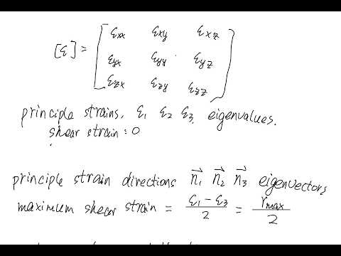
- Principal strains are the eigenvalues of the 3×3 strain tensor, and their eigenvectors identify the principal orientations.
- The 1D equation σ = Eε is limited to linear-elastic tension or compression; general 3D elasticity requires coupled normal-strain relations.
- For isotropic materials, shear strain follows γ = τ/G and G = E/[2(1 + ν)], so only Young’s modulus and Poisson’s ratio are independent elastic constants.
- In isotropic linear elasticity, principal stress and principal strain directions coincide, allowing stress and strain eigenvectors to be compared directly.
Chapters
- The rubric assigns credit for identifying the critical location and calculating stress contributions from axial tension, bending, transverse shear, and torsion.
- Stress components must be placed in the correct positions of a 3×3 stress matrix before calculating principal stresses.
- A consistent solution based on the wrong critical point can still earn 17 points; a propagated arithmetic error or repeated unit error is penalized once.
- Sign errors, incorrect subscripts, and adding a stress component that should be zero receive separate deductions.
- For an initially perpendicular pair of sides in the xy plane, shear deformation reduces the 90° angle by the sum of rotations θ₁ and θ₂.
- The rotations come from displacement changes over lengths Δx and Δy; taking the limits gives ∂v/∂x and ∂u/∂y.
- Under the small-deformation assumption, tan θ ≈ θ, so engineering shear strain is γxy = ∂v/∂x + ∂u/∂y.
- The same displacement-gradient construction applies to γyz and γzx using the corresponding displacement components.
- Engineering shear strain γxy is the sum of two displacement gradients, while the corresponding tensor strain entries εxy and εyx are each half of γxy.
- The strain tensor is a symmetric 3×3 matrix, paralleling the symmetry of the stress tensor.
- Ting Dong recommends finding principal strains by calculating the eigenvalues and eigenvectors of the strain matrix rather than memorizing long transformation formulas.
- The example starts with a square whose corners A, B, and D move while C remains fixed, illustrating how a displacement field determines local strain.
- Normal strains follow the displacement derivatives εxx = ∂u/∂x and εyy = ∂v/∂y; the stated field makes these zero, as are the z-direction components.
- The only nonzero strain component considered is γxy = ∂v/∂x + ∂u/∂y, calculated directly from the field’s gradients.
- The eigenvalues of the 3×3 strain tensor are the principal strains, and their eigenvectors give the principal strain directions.
- When deformation is the design concern, the principal direction identifies an orientation associated with maximum normal strain.
- The maximum tensor shear strain is half the difference between the maximum and minimum principal strains; the corresponding engineering shear strain is twice that tensor value.
- At principal orientations, shear strain vanishes, and the three principal directions are orthogonal.
- The relation σ = Eε applies only to one-dimensional tension or compression within the material’s linear-elastic range.
- A metal stress-strain curve includes a proportional limit, yield strength, plastic deformation, maximum stress, necking, and eventual fracture.
- For a general 3D state, normal strain in one direction can depend on stress in all three directions, so a single scalar modulus is insufficient.
- Because the stress and strain tensors are symmetric, each can be represented by six independent components and related through a 6×6 constitutive matrix.
- For isotropic materials, normal stresses couple to normal strains through Young’s modulus and Poisson’s ratio, while shear stresses relate to engineering shear strains through G.
- The normal-strain equations include lateral contraction: tensile stress in the y or z direction contributes negative strain in the x direction through Poisson’s ratio.
- The isotropic compliance equations calculate normal strain from the three normal stresses; the inverse stiffness relation calculates stress from known normal strains.
- Engineering shear strain follows γxy = τxy/G, with analogous relations for the yz and zx planes.
- Young’s modulus and Poisson’s ratio determine the shear modulus through G = E/[2(1 + ν)], leaving only two independent elastic constants for an isotropic material.
- Stress-to-strain conversion supports deformation estimates from loads, while strain-to-stress conversion supports force estimates under displacement constraints.
- Ting Dong explains that for isotropic linear elasticity, a principal stress orientation has no shear stress and therefore aligns with a principal strain orientation.
- The corresponding principal stresses and strains share directions; the lecture suggests checking this by calculating both tensors’ eigenvectors.
- The lecture closes by recommending a homework check of principal stresses, principal strains, and their directions.
Transcript excerpt
0:00 Yeah. >> Tennis. >> A tennis. >> A tennis. >> Um a tennis. >> Um so some some students ask me about the gradient rubric. Oh, I have put it here grading rubric for our quiz problem. Um, first identify the correct critical location um is five point uh and calculate each component. Normal stress
0:49 caused by tension 20. Normal stress caused by bending 20. uh add this true term as sigma ax uh five points sheer stress caused by torsion turning point. So basically for calculating each components is turning point each. Um put all this into the matrix 3x3 matrix correctly including put the sigma xs here and to xz to zx here um 10 points calculating value which is uh which are the principal stresses uh 20 points um calculation error I try to minimize um so if let's say if you have your calculation error at the very beginning that's one point one point off and we were not gonna Because if you have this
1:38 calculation wrong basically you have this number wrong you have this number wrong if you have this number wrong and all the following numbers are wrong but we only do the penalty once uh as long as the following step you have the correct understanding uh we will not like double count this single calculation error so that is calculation error wrong unit if you have wrong unit at one place he probably have wrong unit at everywhere so we only give one point for the wrong unit uh even if it's multiple places um and now In this area, MC FI and TC of J uh if you have the wrong moment, run area, run moment inertia, run polar moment inertia, C and wrong torque is 5. H 5. H um and wrong
This is the start of the transcript. Save this video free for the whole transcript, searchable and time-coded.
Related notes
Summary, takeaways, and chapters were generated by AI from the video's transcript and may contain errors. The video belongs to its creator, Ting Dong.