EAS4200, Aerospace Structures, Lecture 25, 2026 Fall
 Watch on YouTube →
Overview
Ting Dong explains how fracture mechanics estimates fatigue-crack growth and remaining useful life, using Paris law, a critical crack size, and an example that sets an allowable crack threshold for 100,000 cycles. The lecture then introduces shear flow in thin-walled aerospace structures, reviewing circular-shaft torsion before deriving displacement relations and identifying the nonzero shear-stress components for a general cross-section.
Key takeaways
- Paris law, da/dN = C(ΔK)^m, estimates fatigue-crack growth in the stable-propagation region and can be integrated from a detected crack size to the critical fracture size to estimate remaining cycles.
- A compressive minimum stress is treated as noncontributing to crack propagation, so the effective fatigue stress range is based on the maximum tensile stress.
- The critical crack size and geometry factor β are coupled because β depends on crack size; a full solution iterates, while the class uses a β = 1 estimate followed by one geometry-based update.
- For a specified 100,000-cycle service interval, the allowable crack size is the initial detected size ai, while the final crack size af remains the fixed fracture endpoint for the given material and maximum stress.
- The worked example produces an allowable initial crack size of 0.063 in using β = 1.1 and a stress range of 32,000; cracks at or above that size need intervention to satisfy the target interval.
- For torsion of a general cross-section, the small-angle displacement field is u = -θzy and v = θzx, and the setup identifies τzx and τzy as the nonzero stress components.
Chapters
- Fracture mechanics tracks crack size and is useful for aircraft maintenance because inspectors assess cracks that already exist.
- The crack-growth curve has initiation, stable propagation, and unstable propagation regions; below the threshold stress-intensity range ΔKth, growth is treated as negligible.
- Fracture occurs when the stress intensity reaches the material's critical value, KIC, defining the final crack size.
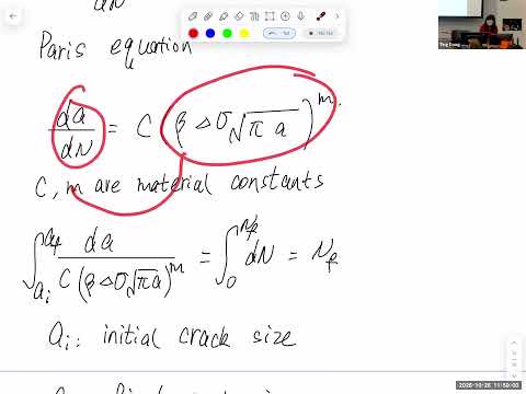
- In the stable-growth region, the straight line on a log-log plot is modeled by Paris law: da/dN = C(ΔK)^m.
- The stress-intensity range is ΔK = βΔσ√(πa), with β determined by geometry and C and m determined experimentally for the material.
- Integrating from the detected initial crack size ai to the critical final size af yields the cycles remaining until failure, not the crack's total lifetime from initiation.
- For crack-growth calculations, a compressive minimum stress is ignored, so the effective stress range becomes the maximum stress.
- The critical final crack size is calculated using the maximum stress and material fracture toughness because that stress is the most severe point in the cycle.
- Because β depends on crack size while af depends on β, the standard approach iterates; the class's simplified method assumes β = 1, recalculates af, then updates β once.
- The one-update example does not converge, but Ting Dong accepts it for the course's subsequent remaining-life calculation.
- KIC has units of stress times the square root of length, such as ksi√in or MPa√mm, consistent with KIC = βσ√(πaf).
- Paris constant C's units follow from da/dN = C(ΔK)^m; they vary with the units used for crack length and stress.
- β is not a universal value: the appropriate geometry chart depends on features such as holes, grooves, fillets, bending, and crack location.
- The practical inspection question is to determine which observed crack sizes can remain unrepaired while the structure survives another 100,000 cycles.
- The target 100,000 cycles is remaining useful life starting when an inspector detects the crack, not total life from the moment the crack initiated.
- For fixed material and maximum stress, af is the fixed fracture endpoint; the allowable observed crack size is ai, which must grow to af over the specified interval.
- The same Paris-law integral is rearranged to find the initial crack size that reaches the known final crack size after 100,000 cycles.
- Using the example's β = 1.1 and stress range of 32,000, the calculated allowable initial crack size is 0.063 in.
- Cracks smaller than 0.063 in have more than 100,000 cycles of estimated remaining life; cracks at or above the threshold require action to meet that service interval.
- The lecture shifts to shear flow, a topic Ting Dong describes as especially challenging and central to aerospace structural design.
- Aircraft fuselages, airfoils, and many internal components are thin-walled and generally noncircular, unlike the circular shafts emphasized in introductory mechanics of materials.
- Airfoil torque can arise from extended leading-edge or trailing-edge flaps and from nonuniform lift, making torsional shear important for wings as well as fuselages.
- For a circular shaft, the mechanics-of-materials relation is τ = Tr/J, and the shear constitutive equation is γ = τ/G.
- The deformation geometry gives γmax = αC/L, where α is the end rotation, C is the shaft radius, and L is shaft length.
- Combining the relations gives α = TL/(GJ); with unit twist θ = α/L, the torque relation becomes T = GJθ.
- For a general cross-section in the xy-plane and shaft axis z, a point P at coordinates (x, y) moves when the free end twists by α.
- Small-angle geometry gives the transverse displacements u = -αy and v = αx; substituting α = θz gives u = -θzy and v = θzx.
- The derivation focuses on torque alone, excluding axial loading and bending so the normal stress and normal strain components are set to zero.
- With z as the shaft direction, the torque-induced shear components lie on planes involving z: τzx and τzy, with corresponding shear strains γzx and γzy.
- The xy shear components are set to zero in this torque-focused setup, leaving τzx and τzy as the only nonzero stress components identified so far.
- The derivation is paused at 46:51 for continuation in the next class; the recording's remaining tail contains no additional instructional derivation.
Transcript excerpt
0:00 That's all. >> How was the exam? On Friday night. Was too difficult, too easy? It's okay? Okay. Um I I I will I will show the solution is next class. Um So, solution and grading rubric next class. Um So, let's continue with the topic we talked >> [clears throat] >> before the exam. So, we use the fracture mechanics method for to model our fatigue crack propagation. Um and I would consider that in the aircraft structure, this one is more relevant for
0:49 us because it make the crack size involved. For the stress life method, um I would say it's more to the mechanical design. But for aircraft structure, this one probably is more relevant because whenever we do a maintenance repair, it's always we see the crack size first. So, um that's why we had this So, this is a model that based on experimental data in from the lab. We have the initial phase and the stable propagation and unstable propagation. And we have the Y axis as the crack growth rate, A as crack size, and N as number of cycle to failure. dA/dN is crack size growth per cycle. So, it's also considered crack growth rate. Uh stress intensity factor,
1:37 we have the beta sigma square pi A. A crack size, sigma stress level, and beta based on the geometry. Um It's the stress intensity modification factor. Delta K, of course, if you replace this sigma as delta sigma for the in the fatigue situation, it become delta K range. That is the X axis here. And we have a threshold value that is considered if you lower than this threshold value there's no crack propagation and the propagation start at delta K th. Th means threshold. So, three phase crack initiation, stable propagation,
This is the start of the transcript. Save this video free for the whole transcript, searchable and time-coded.
Related notes
Summary, takeaways, and chapters were generated by AI from the video's transcript and may contain errors. The video belongs to its creator, Ting Dong.