EAS4200 Aerospace Structures, Lecture 28, 2026 Fall
 Watch on YouTube →
Overview
Ting Dong derives torsional behavior for a thin narrow rectangular section using a stress function, obtaining the torsional constant J = Bt³/3 and maximum shear stress τmax = 3M/(Bt²), where B is the long dimension, t is thickness, and M is applied torque. The lecture applies these results to a plate with dimensions 240 mm by 16 mm, length 400 mm, shear modulus 80 GPa, and 15° end rotation, then shows how to sum torsional constants for open sections assembled from narrow rectangular elements.
Key takeaways
- For a narrow rectangular cross-section with B ≫ t, the stress-function derivation gives J = Bt³/3.
- Shear stress varies linearly through the thickness and reaches its maximum magnitude at x = ±t/2, giving τmax = 3M/(Bt²).
- A specified free-end rotation must be converted to radians and divided by bar length to obtain twist per unit length before calculating torque with M = GJθ.
- For an open thin-walled section assembled from narrow rectangular elements, add each element’s Bt³/3 contribution to obtain the total torsional constant.
- The parallel-axis theorem is needed for many composite bending calculations but not for summing torsional constants of open narrow-strip components.
Chapters
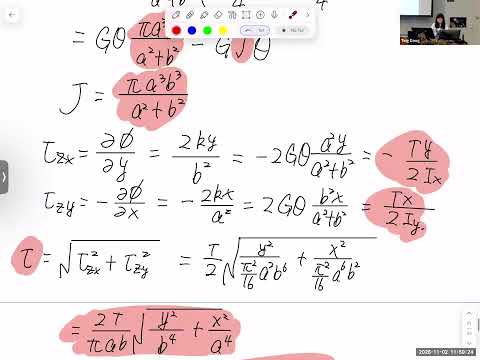
- The prior stress-function method for elliptical sections also applies to circular sections; the homework requires deriving the circular result rather than quoting τ = Mc/J.
- Nonuniform airfoil lift and deployed leading- or trailing-edge flaps can create torque on wings as well as fuselages.
- Aircraft structures prioritize low weight and may use a safety factor near 1.5, making torsional stress important in thin structural elements.
- The example uses a rectangular cross-section of long dimension B and thickness t, assuming B ≫ t.
- With x through the thickness and y along the width, the two short end surfaces are neglected under the narrow-strip approximation.
- A stress function proportional to 1 − 4x²/t² satisfies the zero-stress-function boundary condition at x = ±t/2.
- Applying the governing stress-function equation identifies the coefficient as K = Gθt²/4, where θ is twist per unit length.
- Integrating the stress function over −t/2 ≤ x ≤ t/2 and −B/2 ≤ y ≤ B/2 gives the torque relation.
- Equating the integral to GJθ yields the narrow-rectangle torsional constant J = Bt³/3.
- Differentiating the stress function gives one zero shear-stress component and a nonzero component that varies linearly with x.
- The stress magnitude can be written as τ = 2Mx/J, with M the applied torque; its sign changes across the strip centerline.
- At the top and bottom surfaces, |x| = t/2, so τmax = Mt/J = 3M/(Bt²).
- The worked bar has width A = 240 mm, thickness b = 16 mm, length L = 400 mm, and shear modulus G = 80 GPa.
- A 15° rotation is specified at the free end, while the requested quantity is maximum shear stress.
- Because torque is not given directly, the solution first uses the torsion relation M = GJθ.
- Convert 15° to radians using 15π/180 before using the torsion equations.
- The twist per unit length is θ = φ/L, where φ is the total free-end rotation and L = 0.4 m; it is not the total rotation itself.
- Calculate J = Ab³/3 using dimensions in meters, then use G = 80 × 10⁹ Pa to find torque and substitute it into τmax = 3M/(Ab²).
- For an open section made of narrow rectangular elements, the total torsional constant is the sum of each element’s Bt³/3 contribution.
- A T-shaped section with flange dimensions B₁, t₁ and web dimensions B₂, t₂ has J = B₁t₁³/3 + B₂t₂³/3.
- Unlike composite bending calculations, this torsion calculation does not require the parallel-axis theorem.
- For each narrow rectangular element, use its larger cross-section dimension as B and its smaller dimension as t.
- Bending or curving a strip does not change its torsional constant if its B and t dimensions remain unchanged.
- The class distinguishes these additive open-section results from closed-section torsion, which is reserved for later coverage.
Transcript excerpt
0:00 So, in the last class, we talked about the how to derive the J torsional constant, shear stress distribution, maximum shear stress for a elliptical shape. But, of course, this method you can use derive any kind of cross section. And I think in the homework, the first problem is it is derive a circular cross section. You need to use this method. So, don't just use what you have from the mechanics materials like the tau equals TC over J and give that directly. You need to derive that one. So, use the same method, you come up with the equation of this one, the phi function for the circle, and then you start from here to identify K and T equal to double
0:49 integral of this phi function over the cross section equal to GJ theta to derive J, and the same thing, use the definition of the phi function derive the stress distribution um the two components and put them together become the shear stress distribution in terms of the X and Y and find the maximum value. So, the procedure wise should be same as this one. You shouldn't You're not You're not supposed to use the conclusion equation from the mechanics materials directly. It's It's a different purpose now. Um And in the class, we did an example that how if we have a cross section with circular cross section and elliptical cross section, how do we check if the same rotation would have maximum shear stress or if it can resist the same shear stress? Sorry, resist same torque, what which one has
1:37 higher? For the same shear stress, which one has can resist higher torque? So, today we're going to talk about a new cross section. So, I'm in this figure here. So, basically,
This is the start of the transcript. Save this video free for the whole transcript, searchable and time-coded.
Related notes
Summary, takeaways, and chapters were generated by AI from the video's transcript and may contain errors. The video belongs to its creator, Ting Dong.