CE351 lec37 SD card and SPI
Overview
Yiyan Li explains why high-speed sampling to an SD card requires writing raw 512-byte blocks instead of relying on Arduino's file-oriented SD.h workflow, which can take roughly 15 to 50 milliseconds per write. The lecture covers SPI wiring and 3.3 V level shifting, PCB practices for impedance matching and decoupling, block addressing, and how to stream blocks continuously before sending recorded data to a computer for analysis.
Key takeaways
- A file-oriented SD.h write that takes 15 to 50 milliseconds cannot keep up with a 40 kHz sampling stream; buffering and low-level 512-byte block writes are required.
- For a multi-block transfer, start once before the loop, stream blocks inside the loop, and stop once afterward so the driver can advance block addresses automatically.
- A 512-byte SD card block uses byte offsets 0 through 511, while a block number identifies the sector and is not itself a byte address.
- A 5 V Arduino output should be level-shifted before reaching a 3.3 V SD card, but the SD card's 3.3 V MISO output can be read directly by a compatible 5 V microcontroller input.
- A 100-nanofarad ceramic capacitor near every IC VCC pin and a short via connection to ground help reduce supply noise; a regulator output may also need a bulk capacitor around 10 microfarads.
- To match a 50-ohm trace to a 17-ohm driver output impedance, the lecture's example uses about 33 ohms of series resistance placed near the driver.
Chapters
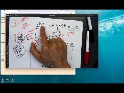
- Arduino's SD.h file workflow may take roughly 15 to 50 milliseconds to open and write, too long for the lecture's high-speed sampling task.
- The sampling example uses a 25-microsecond interval, equivalent to about 40 kHz, and groups data into blocks.
- SD cards are accessed in 512-byte blocks, also called pages, even though SPI transfers the data byte by byte.
- The class uses the SdFat library's lower-level block operations instead of relying on file-oriented writes.
- Yiyan Li outlines three tutorial tasks, with most code supplied and only limited sections left for students to complete.
- Task two is expected to work once the SD card circuitry and buffer are soldered correctly.
- The main goal is hands-on experience with SD card blocks, sampling rate, bandwidth, and reading and writing data.
- The four SPI signals are chip select, clock SCK, MOSI, and MISO; SS and CS both refer to chip selection, which is usually active low.
- SPI connects matching signal names between the microcontroller and SD card, with MOSI carrying data from the master and MISO returning data.
- The SD card uses 3.3 V logic, while the Arduino pins discussed use 5 V logic; a buffer or level shifter reduces the outgoing signal level.
- The buffer passes signals from its A inputs to its Y outputs only, so an SD card's MISO output must not be routed through it backward.
- Impedance mismatch can distort fast digital edges through reflections, making a square wave show bumps and dips.
- For a 50-ohm trace and a driver with 17-ohm output impedance, the example adds about 33 ohms in series near the driver.
- Place a series matching resistor close to the signal-driving device, such as the microcontroller, rather than midway along the trace.
- The lecture cautions that the SD card module's 3.3-kilohm resistors are large for this purpose and can slow signal transitions.
- The LP2985 regulator supplies 3.3 V for the SD card circuitry; the lecture identifies its package as SOT-23-5.
- Place a 100-nanofarad ceramic decoupling capacitor close to each IC's VCC pin.
- Keep the capacitor's ground path short and connect it through a nearby via to the PCB ground plane.
- Place the capacitor so the supply route reaches it before the IC's VCC pin when practical.
- A 512-byte block contains byte offsets 0 through 511.
- For a 16 GB card, divide total capacity in bytes by 512 to calculate the number of blocks; the final byte address is total bytes minus one.
- The SPI master, called the leader in the lecture's terminology, supplies the clock and asserts chip select to choose a peripheral.
- The legacy MOSI and MISO names mean Master Out, Slave In and Master In, Slave Out; newer signal naming may use SDI and SDO.
- File-oriented SD.h opens a file before writing, adding latency that conflicts with continuous high-speed sampling.
- The class uses SdFat and block-level operations to write and read SD card sectors directly.
- The board's level shifter converts 5 V microcontroller outputs to 3.3 V logic for the SD card; it is not a power regulator.
- For a 50-ohm trace and 17-ohm driver output impedance, the example's series resistor is approximately 33 ohms and belongs near the driver.
- A multi-block write uses three stages: start at a block number, repeatedly write data, then stop once the transfer is complete.
- Start the write operation outside the loop and write successive blocks inside it; the driver advances the block number automatically.
- The example writes a designated number of blocks, such as 128, before stopping.
- Starting and stopping inside every loop iteration can still write data, but adds overhead and requires manually advancing the block number.
- Continuous reads follow the same start-once, read-repeatedly, stop-once pattern as continuous writes.
- Recorded data is typically sent over a serial connection to a computer, where it can be saved as CSV and analyzed with Python or MATLAB.
- Avoid loading a large recording into the microcontroller's limited RAM; the lecture notes that a 512-byte buffer can be overwritten as data is streamed.
- The same block-streaming approach applies when reading data back from the card.
- Yiyan Li recommends starting the tutorial work with the supplied code, since most of the implementation is already provided.
- The essential concepts to practice are 512-byte block access, continuous SD card reads and writes, and the relationship between sample rate and bandwidth.
- The tutorial is the final one in the class, with students expected to focus most of their remaining effort on the project.
Transcript excerpt
0:00 options. Okay? Either use your laptops through serial monitor, save the data to the C CSV file, and and or you directly store everything on the SD card. So uh the major task for this tutorial seven, right? Is to learn um how to save data to to the SD card. So there are there are two options. If you find some online resources for especially for the Arduino platforms, they have a header file called sd.h. And usually that's for beginners um to to use. They don't really care about the speed. Okay? So it's SD .h something like this. You see this everywhere.
0:47 You see this everywhere. Um and and we cannot use it. The thing is when that if you are using SD .h, it opens a file first and then write to it. Write to the card. So this takes about like 15 to 50 milliseconds in general. Okay? Um but for our case at that point you you can you can slow down the sample rate, right? Just in case that the 25 microseconds interrupt the ADC that we have been using uh since a few weeks ago, right? Is that 40 kHz?
1:37 It's about 40 kHz, right? Or 400 kHz? 40 kHz. So for this sample rate, for example, this is required. Okay? You cannot slow it down. If it's 25 microseconds times 5 uh 12 per block, so it's another concept. So in the SD card it's it's separating um the the entire SD card space by blocks. No matter what the size is, for example, 16 gigabytes, or maybe 32 gigabytes for the card I just gave to you guys, right? So the modern modern ones are pretty big. And they are separated by blocks or we can say pages. And every block or every page is
This is the start of the transcript. Save this video free for the whole transcript, searchable and time-coded.
In this course
Related notes
Summary, takeaways, and chapters were generated by AI from the video's transcript and may contain errors. The video belongs to its creator, Yiyan Li.