CE351 lec7 The Morse code and time delay in MCUs
 Watch on YouTube →
Overview
Yiyan Li explains how CE351 students can calibrate MCU time delays with a NOP-based loop, oscilloscope measurements, and linear regression, then use the calibrated delay to generate Morse code. The lesson connects board pin mapping and audio-amplifier wiring to Arduino button detection, Morse timing rules, and an array-based encoder for letters A through Z.
Key takeaways
- Arduino digital pin numbers, MCU port names, and physical chip pin numbers are distinct: PH5 and PH6 map to digital pins 8 and 9 and chip pins 17 and 18.
- NOP-loop timing must be measured on the actual MCU: oscilloscope readings for 4,000, 10,000, and 20,000 iterations can be fitted to estimate the loop count needed for a target delay.
- Morse timing depends on ratios: dot is one unit, dash is three, intra-letter gaps are one, inter-letter gaps are three, and word gaps are seven units.
- A simple digital output can encode Morse timing but may produce only speaker transients; tone() and noTone() add audible high-frequency oscillation.
- A 26-by-5 numeric lookup array can encode A through Z compactly, with character subtraction from 'A' selecting the row and a sentinel index ending playback.
Chapters
- The tutorial combines measuring software-generated delays with coding Morse output for an LED or speaker.
- On the board pin map, PH5 and PH6 correspond to Arduino digital pins 8 and 9, but chip pin numbers 17 and 18.
- Use the schematic and pin map together: port names, Arduino digital pin numbers, and physical chip pin numbers are different identifiers.
- The first demonstration sends timed on/off signals to an LED so the Morse durations can be seen.
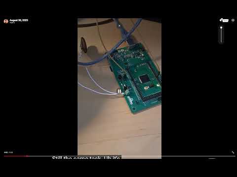
- For speaker output, connect the MCU output to the audio amplifier's PRE input and connect the speaker to the board's speaker terminals.
- A jumper on the right-side header routes the signal to PRE while bypassing the low-pass filter.
- A simple HIGH/LOW output creates a brief speaker transient, followed by silence during the programmed delay.
- Arduino's tone() and noTone() functions generate and stop a high-frequency oscillation, producing a more audible sustained beep.
- Both output methods can represent the same Morse timing; the oscillating tone is the more conventional audible signal.
- The push-button input is read with digitalRead() using the defined button pin, such as digital pin 9.
- The button circuit is pulled high when unpressed, so a while loop waiting for HIGH holds execution until the button changes state.
- Place the remaining program logic inside the main loop's braces so it runs after the button condition is satisfied.
- The example uses digital pin 9 for the PH6 button input and digital pin 3 for output; consult the board labels to locate each connection.
- Connect the output either to an LED for visual timing checks or to PRE for audio playback.
- The lab measurement sends the output signal to an oscilloscope and uses its cursors to read the period.
- A NOP assembly instruction performs no useful work but consumes processor time, making repeated NOPs a basis for a software delay.
- Measure three loop sizes, 4,000, 10,000, and 20,000 NOP iterations, then fit iteration count against measured time with linear regression.
- Convert oscilloscope readings from milliseconds to microseconds before fitting; the example reports about 1,860 microseconds for 4,000 iterations.
- Use the fitted equation to estimate the iteration count for the target delay rather than assuming another MCU has the same timing.
- A Morse dot lasts one time unit, while a dash lasts three time units.
- The gap between marks within a letter is one unit, the gap between letters is three units, and the gap between words is seven units.
- The time unit is configurable, so changing one base value adjusts the speed of the entire message.
- The code defines a button input and an output pin that can drive either an LED or the speaker input.
- A nested loop builds a calibrated delay from repeated NOP operations; the example starts with nine NOPs per inner iteration, but calibration may change that value.
- The setup() function configures input and output pins, while loop() waits for a button press before processing the selected message.
- The report should include the measured data and regression rationale supporting the chosen delay constants.
- The Morse lookup table stores 26 letter rows with up to five dot-or-dash entries per row, matching the longest letter codes.
- Dots and dashes are represented as compact numeric values, such as 0 for a dot, so the playback function can test them with conditionals.
- The playback function turns the output on for one or three time units, turns it off, and inserts the inter-mark delay.
- A column index advances through each letter's marks and is set to five when the code ends, preventing further array processing.
- Convert an uppercase character to a lookup-table row by subtracting 'A': A maps to index 0, B to index 1, and so on.
- The conversion function returns the calculated index as an unsigned 8-bit integer.
- Students were asked to finish and submit the in-class work, then meet in lab to measure delay timing; the following tutorial introduces timers.
Transcript excerpt
0:00 actually midnight today. Um, so you can keep working on it without getting uh losing any points. Okay? Hopefully you can finish everything today by the end of today. And um another in class on Friday uh and so homework four will be due next Sunday. So you don't have to worry about that for now. So these are all all the tasks for this week. So you expect you can expect what are going to be covered um within this seven days right then click tutorial number one the number one and for the first couple of tasks if you look at your in class okay your in class so these are pretty fundamental questions for [clears throat] the
0:48 materials covered in the tutorial one uh but I still list it over here to help you guys pay attention and understand what's really going on with the code okay within the And if you look at the top, you see the ASM right the nuts. So this is an assembly uh instruction. It just doing nothing. Just waste a little bit of time over there. It's doing nothing. And but we are using this one to form a certain amount of time delay for this tutorial. And there will be some measurements following uh this tutorial to let you u uh test how long um how how many knobs are needed to form like one second time
1:35 delay over there. Okay. And by if you look at the first question right find the digital pin number uh and the chip pin number for these two physical pins and used for push button top and bottom. So the way to approach this problem is you have to go to the website again. Go to my major website and go to the course website and go to
This is the start of the transcript. Save this video free for the whole transcript, searchable and time-coded.
Related notes
Summary, takeaways, and chapters were generated by AI from the video's transcript and may contain errors. The video belongs to its creator, Yiyan Li.