CE351 lec29 PCB and the Skyboard
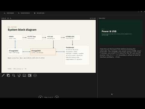 Watch on YouTube →
Overview
Yiyan Li explains how to read the Skyboard PCB schematic and choose components by function, covering USB protection and signal integrity, regulator power and package limits, reset circuitry, UART isolation, and noise filtering. The lecture also compares SPI and I2C and reviews practical design figures, including a 500 mA resettable fuse, 22 Ω USB series resistors, a 170 mW regulator load estimate, and 10 kΩ I2C pull-ups.
Key takeaways
- A regulator’s dropout voltage matters most when the input-to-output headroom is small: a 3.7 V LiPo powering a 3.3 V ESP32 leaves only about 400 mV before the battery voltage declines.
- At a 100 mA load, dropping 5 V to 3.3 V dissipates about 170 mW in the regulator, so the package’s thermal power limit must be checked alongside the electrical rating.
- USB D+ and D− use a nominal 90 Ω differential interface, and series resistors such as the Skyboard’s 22 Ω parts can reduce reflections when selected to suit the driver and layout.
- A 10 kΩ pull-up keeps an active-low reset input inactive, while clamp diodes limit positive and negative voltage transients at the reset node.
- Series resistors on shared UART TX/RX paths limit current if the USB-UART bridge and an external peripheral drive the same line at conflicting levels.
- I2C uses SDA and SCL with pull-ups because its devices use open-drain signaling; long cables add capacitance, so the bus speed, pull-up values, and distance must be considered together.
Chapters
- The board receives 5 V from USB and uses a resettable fuse rated for about 500 mA to protect against excess current.
- An LDO, or low-dropout regulator, provides the lower-voltage rail; its dropout must fit the available difference between input and output.
- A compact sensor example uses a 3.7 V single-cell LiPo to supply a 3.3 V ESP32, requiring an LDO with roughly 200 mV dropout because the battery voltage falls during use.
- The USB connector carries differential D+ and D− data lines, alongside power, ground, and a shield connection.
- Varistors have very high resistance during normal operation, but their resistance falls during a voltage surge, diverting the transient away from sensitive circuitry.
- This surge protection must not load the USB data lines under ordinary operating voltages.
- The USB connector shield is coupled to ground through L1, which the lecture describes as an inductor.
- An inductor passes DC, such as the ground connection, while impeding higher-frequency noise and interference.
- Filtering the shield path can help prevent high-frequency disturbances from coupling into the board’s ground and digital power circuitry.
- Abrupt changes in PCB trace width or impedance can reflect fast digital signals, producing ringing instead of clean square waves.
- USB uses a nominal differential impedance of about 90 Ω; the board’s 22 Ω series resistors help provide source termination and reduce reflections.
- For a different microcontroller or interface, check its electrical specifications rather than assuming the same resistor value is appropriate.
- The regulator converts the board’s 5 V supply to 3.3 V for components such as the SD card interface, which uses SPI.
- At an estimated 100 mA load, a 1.7 V regulator drop dissipates about 170 mW, calculated as voltage drop multiplied by current.
- The selected SOT-23-5 package is described as supporting roughly 200 to 400 mW; regulator package choice must account for heat dissipation as well as fit.
- The microcontroller reset input is active-low, and pressing the board’s reset button pulls the reset node to ground.
- A 10 kΩ pull-up holds reset high during normal operation so noise is less likely to trigger an unintended reset.
- Clamp diodes limit positive and negative transients at the reset node, protecting the microcontroller from voltage excursions.
- The USB-to-UART bridge and the microcontroller share UART TX and RX connections that are also exposed on header pins.
- If an external UART device drives a line while the bridge drives it in the opposite direction, a direct connection could cause excessive current.
- The 1 kΩ series resistors limit contention current and help protect both the USB-UART bridge and connected peripherals.
- Capacitors placed close to IC power pins help shunt high-frequency noise to ground and stabilize local supply voltage.
- The L3 and C19 network forms a low-pass filter for the ADC reference node, reducing noise that could degrade measurement accuracy.
- The lecture gives the LC cutoff relationship as 1/(2π√LC) and an example cutoff near 159 kHz.
- SPI typically uses MOSI, MISO, SCLK, and a chip-select line, often marked SS or CS; it supports higher data rates than I2C.
- I2C uses two lines, SDA for data and SCL for clock, and is suited to slower peripheral communication.
- For a hot-tub temperature-monitoring example, the sensor digitizes temperature locally before sending digital data onward, avoiding the noise sensitivity of long analog runs.
- I2C lines require pull-up resistors because devices use open-drain signaling and pull the bus low rather than actively driving it high.
- The Skyboard uses 10 kΩ pull-ups on SDA and SCL; the correct value depends on bus capacitance and operating speed.
- The lecture distinguishes SPI’s faster clocked links from I2C’s two-wire bus and previews a Friday PCB quiz with about 20 single-choice questions.
Transcript excerpt
0:10 All right. So that's uh slides over here for the PCB design. Um I there might be somewhere around like 20 questions on the quiz on Friday for PCB design observations. So today's lecture is recorded but all these all these questions are uh single choice. So you you are provided with the four options. You'll pick up one. So 20 questions 20 something questions is not a big deal I think. Um so something that we need to um need to know. Okay. So first it's a provides a USB power to it, right? And it's five volts for USB uh always. And at the very beginning of the schematics, there's a there he is. Um there's a fuse. [laughter]
1:03 Um that's a really interesting device. So the material recover most of the cases a fuse breaks. It breaks it breaks, right? But for these fuse it breaks and when it cools down it recovers itself and the current limit for that fuse is 500 milliamps. So where that is It does shows the picture. So, I'm going
1:49 just to display this guy, right? So, we'll see the fuse in a bit. Okay. And uh it's a 5 volts power rail, which means realtore power voltage difference is 5 volts from uh VDD to to ground. So, we don't have negative voltages over there. And there's a LDO. So on the quiz you it's going to ask you what the LDO is, right? It's a low dropout um regulator. So dropout voltage is difference between the uh supply voltage to the output voltage of the regulator. Um so uh there are some requirements about which type of LDO to be to be used. Um so one important uh consideration is height room uh between
2:37 the um so so between the supply voltage and
This is the start of the transcript. Save this video free for the whole transcript, searchable and time-coded.
Related notes
Summary, takeaways, and chapters were generated by AI from the video's transcript and may contain errors. The video belongs to its creator, Yiyan Li.