CE351 lec4 PCB Assembly
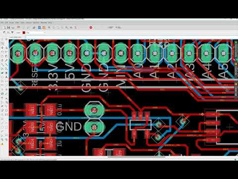 Watch on YouTube →
Overview
Yiyan Li walks through preparing and assembling the Skywire PCB, from opening course design files in Eagle or Fusion 360 to identifying mislabeled components in the original board file. The main practical guidance covers assembly order and hot-air soldering: solder low-profile parts first, carefully align a 100-pin chip, and take extra care with the USB interface chip because overheating can lift its tiny pads.
Key takeaways
- When Skywire PCB labels do not match component locations, the original Eagle board file provides reliable identification through the selected component's Properties and part number.
- Eagle PCB and Fusion 360 can both open the course PCB designs, but Eagle is the more direct choice for following Yiyan Li's existing tutorials.
- A height-based assembly order improves iron access: solder surface-mount and other low-profile components before taller components.
- For the 100-pin chip, flux, a thin solder coating, correct notch orientation, and hot-air reflow allow surface tension to help align the pins.
- The USB interface chip is particularly risky to solder because its contacts are hidden underneath and excessive heat can lift its tiny PCB pads.
- Use tweezers rather than fingers to handle ICs, and inspect cooled solder joints under a microscope before removing any bridges.
Chapters
- Download and extract the Skywire board files from the course website to access the schematic and PCB layout.
- Open the design in Eagle PCB or Autodesk Fusion 360, which is installed on school computers and also supports PCB design.
- For an Eagle startup bug on Windows, follow the course instructions to locate the specified DLL file and add a .bak extension; enable file extensions first if needed.
- Eagle tutorials are available on Yiyan Li's website, while Fusion 360 has a similar workflow but a different interface.
- The current board labels can be misaligned, so use the original Eagle board file when a component's location or identity is unclear.
- In the layout, red traces indicate the top layer and blue traces indicate the bottom; the class components are mounted on top.
- Select a component's crosshair and open Properties to read its part name, such as OPA344N, then match the name to the labeled parts drawer.
- The board file distinguishes component objects from nearby drawing lines and copper traces, which can otherwise be selected by mistake.
- Solder surface-mount resistors and capacitors first, then push buttons and other short components, and finish with taller parts so they do not block iron access.
- For the 100-pin chip, apply flux, coat the PCB pads with a thin layer of solder, place the chip with tweezers, and verify the notch and pin-1 orientation.
- Heat the chip from above with a hot-air nozzle; after roughly 5 to 10 seconds, molten solder and surface tension can pull slightly misaligned pins into position.
- Inspect pins under the digital microscope after cooling; remove solder bridges with a brief swipe of the soldering iron, and avoid handling sensitive ICs directly to reduce static-discharge risk.
- The small USB interface chip converts USB D+ and D− signals to UART RX and TX and also supplies power to the system.
- Apply flux and a controlled solder coating to the pads, align the chip's notch with the board marking, then reflow it with hot air.
- Because its contacts are underneath the package, use tiny tweezer adjustments while the solder is molten; the solder's surface tension can pull the chip back into alignment.
- Limit heating time because the small copper pads are bonded to the board with epoxy and can detach if overheated; testing this chip early can prevent redoing the rest of the board.
Transcript excerpt
0:00 decided to not to discontinue supporting on uh this version of the board. So, we didn't update the layout. So, some some of the labels are a little bit misaligned with the real parts, which can cause problems and confusions. But, however, there's another way to figure that out. If you go to the website, you can find out go to tutorials. Uh no, not tutorials. Um So, go to the course website and you download Skywire about files. Okay, it will be downloaded. It's going to be a zip folder here. And let's use it. The zip folder can be extracted, and you will eventually see the schematic and the board file, the two
0:47 files. And it requires Eagle PCB to open them up, but the the school computer installed Fusion 360. It's from Autodesk. Fusion 360. A lot of people do 3D printing with it, right? And that also has a PCB design environment in that software. So, you can open up your schematic and layout in that software if you don't want to use Eagle PCB. So, Eagle has been very popular in the past many years, but just most recently, Autodesk uh decided to move everything into from uh Eagle PCB to Fusion 360. So, if you know how to use Eagle, it probably only take like 20-30 minutes to try to be used to the environment in uh Fusion 360. It's 360. It's specifically a little bit better into that kind of bigger
1:34 software environment. It's a still the same thing. Um I have a lot of tutorials on Eagle on my website. So, if you really want to just make it easier, just follow Eagle PCB, which is probably with the easiest way to learn how to design PCB uh in this class. So,
This is the start of the transcript. Save this video free for the whole transcript, searchable and time-coded.
Related notes
Summary, takeaways, and chapters were generated by AI from the video's transcript and may contain errors. The video belongs to its creator, Yiyan Li.