CE351 lec28 ADC inclass 9
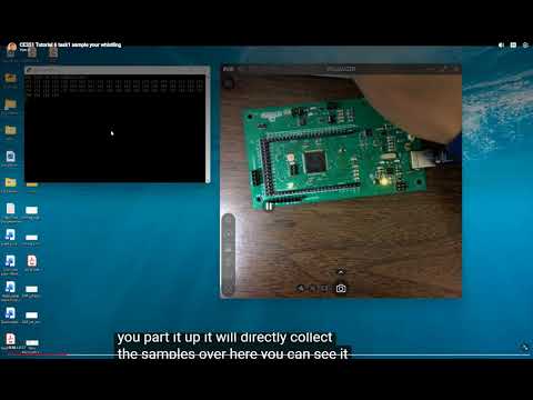 Watch on YouTube →
Overview
Yiyan Li explains two ADC sampling exercises: a timer-driven 64-sample capture and a state-machine-based trigger that records 256 samples after detecting an input outside a 150 to 170 threshold band. The lecture also covers ADC prescaler selection, crossing-based frequency measurement and array bounds, timeout and bias improvements, then introduces Eagle or Fusion 360 PCB design and fabrication expectations.
Key takeaways
- Task 1 stores 64 ADC readings at 25-microsecond intervals, but its completion logic executes after a 65th conversion whose result is discarded.
- Task 2's 160-centered threshold band from 150 to 170 acts as a trigger, not a filter: after the first crossing, the next sample and the following 256 readings are captured.
- A 256-reading buffer and a 32-entry crossing array support at most 31 measured periods; crossing writes need an explicit array-bound check.
- Frequency estimation uses the distance between crossing indices multiplied by the 25-microsecond sampling interval, so noise-induced extra crossings can distort the result.
- A trigger-wait timeout can be implemented by counting 25-microsecond interrupt entries, while a named bias constant makes the code easier to calibrate for boards with different idle readings.
- For PCB work, Eagle or Fusion 360 supports the assignment workflow; manual routing is preferred over autorouting, and panelization with V-scores can lower fabrication costs.
Chapters
- Resetting the microcontroller starts sampling automatically; Task 1 does not require button detection.
- A timer interrupt runs every 25 microseconds, and the loop stops the timer after the sample buffer is filled.
- Reading the ADC low byte first locks the conversion result so the high byte can be read consistently; recording only the high byte is also an option.
- The index reaches 63 while storing sample 64, then a following interrupt performs conversion 65 and enters the completion branch.
- The 65th conversion result is discarded when the timer stops; the buffer still contains exactly 64 recorded samples.
- To capture repeatedly, print the completed buffer first, then restart the timer so later conversions do not overwrite data before it is displayed.
- At one sample every 25 microseconds, 64 samples cover only about 1.6 milliseconds of input.
- Because capture starts on reset rather than a user trigger, begin whistling before resetting the board to improve the chance of sampling it.
- Restarting capture after each print can produce a continuing stream of 64-point buffers.
- Task 2 keeps the ADC interrupt sampling every 25 microseconds while its state machine waits for the F key and a trigger condition.
- With a bias of 160 and a threshold of plus or minus 10, readings within 150 to 170 leave the machine waiting.
- The reading that first crosses the threshold triggers acquisition, but recording begins with the next sample and continues regardless of later threshold crossings.
- The prescaler estimate uses a 16 MHz clock and 13 ADC clock cycles per conversion to determine the maximum prescaler compatible with the target sampling rate.
- The calculation gives a limit near 30, making 16 the next supported prescaler value discussed for the exercise.
- Li compares prescalers 16, 8, 4, and 2, noting that overly fast sampling can capture more high-frequency noise; signal quality should be verified with analysis such as an FFT.
- Task 2 stores 256 ADC readings, indexed from 0 through 255, in limited on-chip memory.
- The code records indices where one reading is below the 160 bias and the next is above it; the number of periods is the number of crossings minus one.
- Shifting 256 right by three bits yields space for 32 crossing indices, which represents at most 31 periods.
- A noisy signal can cross the threshold repeatedly, so adding crossings beyond the 32-entry array can write outside its bounds and corrupt memory.
- Before storing a crossing, check that the crossing count is less than the array size, for example with a size-of-array check.
- Subtract crossing indices to find the number of samples per period, then multiply by 25 microseconds per sample to calculate the period and frequency.
- Inspect printed crossing indices for noise-induced extra crossings before trusting the frequency result.
- If no reading ever leaves the 150 to 170 band after F is pressed, the state machine remains in its trigger-wait state and the main loop can spin indefinitely.
- A timeout can count interrupt entries while waiting; because entries occur every 25 microseconds, the count can represent elapsed time.
- Use a suitable volatile counter, such as a 16-bit unsigned integer, and clear the waiting flag after the chosen limit so the board can resume responding.
- The idle ADC bias is board-dependent: Li observes a value of 160 on the tested board, while another board may idle around 128.
- Measure the resting input on each board and update the threshold center to match its observed bias.
- Replace repeated hardcoded 160 values with one named bias constant or variable so calibration requires changing only one definition.
- PCB submissions are due November 9 so Li can place a fabrication order; shipping and tariffs can cost about $60 even when the boards themselves cost less than $5.
- The PCB tutorial assignment is due the following Monday, and students are encouraged to install Eagle or use Fusion 360 rather than delay getting started.
- A reported Eagle startup issue after the welcome screen has a tutorial-provided file-extension fix.
- The optical-sensor PCB tutorial practices creating a project and schematic, adding a frame and components, and selecting footprints such as 1206 resistors and capacitors.
- A quad op-amp can appear as four schematic units labeled A through D; the tutorial also covers schematic connections and adding a logo.
- Li recommends manual routing because Eagle's autorouter can produce messy traces, and explains panelizing small boards to reduce fabrication cost before separating them along V-scores.
- Students should bring a laptop for the following Wednesday's PCB work; a PCB quiz is planned for Friday.
Transcript excerpt
0:02 first one show one. So the code is mostly given and um so when you start this micro contour we part it up it will directly collect the samples over here. See what I said there whenever you start it it starts collecting. So which means there's no button uh need to be pressed for the for task one. collect the samples over here. You can see it will be turned it to the serial monitor. >> See? >> Uh so the thing is when you >> so what I can do is I I I press the reset button on the board and then it restarts it will directly execute the setup function function and run the run the interrupt to collect the number of
0:50 samples. I think there are how many are there? 64 if I'm right or less doesn't matter though. I mean so it's collect um certain certain number of samples over there. So in that case by having that in your mind and this is the code it's given. Okay it's given. So task number one is given. Um let me show you on the Okay. So you can see we took about all the registers from from last week and
1:40 these are all the setup for the registers. Okay. And there's no button detection mechanism there at all. If you watch the video, you don't really need anything to be detected. And then getting to the loop function. It's checking the if the sampling is complete. Okay, so because the interrupt is uh enabled and this is a really short code. Okay, interrupts enabled and so this will be executed every 25 microsconds 25 microsconds and when the ADC conversion is complete it goes here and sample it. Okay. And like I said, the first one, the lower two bits are
This is the start of the transcript. Save this video free for the whole transcript, searchable and time-coded.
Related notes
Summary, takeaways, and chapters were generated by AI from the video's transcript and may contain errors. The video belongs to its creator, Yiyan Li.