CE351 lec18 IR emitter, transmitter, baud rate
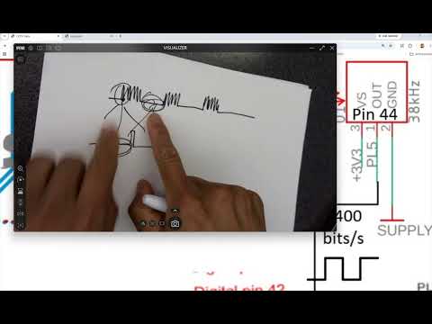 Watch on YouTube →
Overview
The lecture explains how an IR emitter, a 38 kHz carrier, and an integrated receiver-decoder turn light pulses into an active-low digital signal that a microcontroller can read. It connects that signal to UART framing and baud-rate matching, then reviews timer-register configuration for PWM, including ICR as TOP, OCR compare values, and a roughly 10% emitter duty cycle.
Key takeaways
- The IR receiver-decoder output is active-low: detected carrier pulses produce logic 0, while an idle optical path produces logic 1.
- The IR carrier frequency and UART baud rate are different timing parameters; the lecture uses a roughly 38 kHz carrier and a 9600-bit-per-second serial example.
- A standard UART byte frame uses one low start bit, eight data bits, and one high stop bit, totaling 10 bit periods.
- At a 38 kHz carrier, the period is about 26.3 microseconds; a 16 MHz timer uses that period and its prescaler to calculate the PWM TOP count.
- A roughly 10% PWM duty cycle reduces IR LED heating while carrier modulation helps reject ambient infrared interference.
- The IR emitter and receiver both peak near 950 nm, improving optical compatibility between the transmitted light and the detector's strongest response.
Chapters
0:00
IR Emitter and Integrated Receiver-Decoder Basics
- The board pairs an IR LED emitter with a receiver-decoder that converts detected light into a digital output.
- The emitter sends invisible IR pulses that can reflect from room surfaces back to the receiver.
- Avoid staring directly at an energized IR emitter; a sheet of white paper can improve reflections when reception is unreliable.
5:00
The 38 kHz IR Carrier and Active-Low Decoder Output
- The receiver-decoder responds to a modulated IR carrier, described mainly as 38 kHz, although 30 kHz is also mentioned in the lecture.
- Detected carrier pulses make the decoder output logic 0; when no pulses arrive, its output returns to logic 1.
- A white-paper reflector is presented as an occasional signal-strength aid, not a required part of the setup.
8:00
Driving the IR LED with a BJT Switch and Low-Duty PWM
- A BJT acts as a switch: PWM at its base controls current through the IR LED and reproduces the pulse pattern as light.
- The Skyboard application uses approximately 10% duty cycle to limit LED heating and current exposure.
- The carrier’s rapid PWM pulses and the slower data pattern are separate layers of the transmitted signal.
13:00
From Reflected Light Pulses to UART-Readable Data
- The receiver-decoder’s inverted output preserves the transmitted information as a sequence of digital highs and lows.
- A microcontroller can interpret the resulting bit stream when transmitter and receiver agree on the communication timing.
- The lecture distinguishes the IR carrier waveform from the data bits encoded by the longer on/off pattern.
15:00
UART Baud Rate Is Bit Timing, Not IR Carrier Frequency
- UART baud rate sets how quickly data bits are sent; the example default for the Arduino serial monitor is 9600 bits per second.
- At 9600 bits per second, one bit lasts approximately 1/9600 second, or 104 microseconds.
- The 38 kHz IR carrier is not the UART baud rate; confusing the two leads to incorrect timer settings.
19:00
Skyboard UART Routing and Serial Monitor Configuration
- The IR decoder output connects to a microcontroller UART RX pin, while the IR emitter supplies the optical transmission.
- On the Skyboard, UART0 is wired through a USB-to-UART converter to the laptop; Serial.begin(9600) configures the link used by the monitor.
- UART1 can be configured separately for the IR receiver, and its baud rate must match the bit timing generated by the transmitter.
- A baud mismatch between the board and laptop serial monitor can produce unreadable or corrupted characters.
25:00
UART Start Bits, Eight Data Bits, and Stop Bits
- A UART line idles high; a falling edge to low marks the start bit and prompts the receiver to begin sampling.
- A typical frame contains one start bit, eight data bits, and one stop bit, for 10 bit periods per byte.
- The IR decoder output can serve as the UART-like RX signal because no received carrier leaves the output high and detected pulses pull it low.
33:00
UART Byte Framing Compared with SPI
- UART sends bytes with start and stop framing, then repeats the frame for additional bytes.
- The lecture characterizes UART as inexpensive and adequate for low-volume uses such as temperature readings, but less suitable for high-throughput transfers.
- SPI is contrasted as a faster option whose message length can be configured for applications such as communication with storage devices.
37:00
Calculating Timer TOP from the IR Carrier Frequency
- The timer calculation begins with the carrier period, using T = 1/f; at 38 kHz, one carrier period is about 26.3 microseconds.
- For a 16 MHz timer clock, convert the target period into timer counts, then account for any prescaler.
- ICR is introduced as the input capture register, used as the timer TOP value in the discussed PWM configuration.
41:00
Configuring AVR PWM Modes and Output-Compare Registers
- The lecture reviews Timer1 waveform-generation mode bits across TCCR1A and TCCR1B, including the mode 14 configuration.
- ICR sets the PWM period, while an OCR register sets the output-compare point and therefore the duty-cycle behavior.
- The output-compare action changes the pin at compare match and at TOP; register values and output polarity determine the resulting waveform.
- Initialize timer control registers before setting mode bits, compare values, and prescaler settings.
50:00
Receiver Timing, 950 nm Spectra, and Noise Rejection
- The receiver-decoder has a response delay, so UART bit periods must be long enough for the optical signal to be detected and converted reliably.
- The plotted receiver response peaks near 950 nm, and the IR emitter spectrum also has its peak near 950 nm.
- An LED emits a wavelength spectrum rather than a single exact wavelength, even when one wavelength is dominant.
- Modulating the LED with a low-duty carrier helps limit heating and distinguish the desired signal from ambient IR light.
Summary, takeaways, and chapters were generated by AI from the video's transcript and may contain errors. The video belongs to its creator, Yiyan Li.