CE351 lec19 IR transmitter/receiver (no ISR)
 Watch on YouTube →
Overview
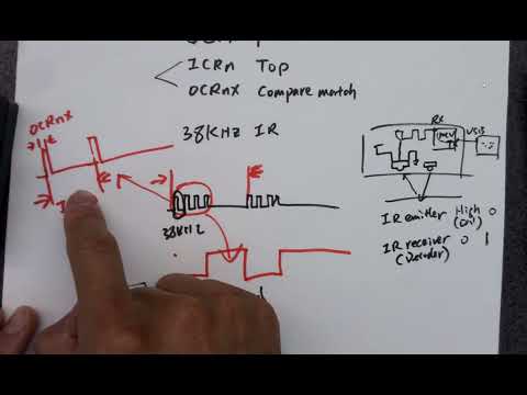
Yiyan Li explains how to transmit UART-formatted data over an infrared link by combining a 38 kHz carrier with a slower data envelope. The design uses Timer 5 PWM on OC5B, with ICR5 setting the carrier period and OCR5B setting its 10% duty cycle, while Timer 3 is polled without an ISR to time the 1200-bit/s envelope; the lecture also covers receiver polarity, LED current limits, pin mapping, and timer-register configuration.
Key takeaways
- The IR link uses two timing layers: a 38 kHz PWM carrier for the emitter and a 1200-bit/s envelope for UART data; these rates must not be confused.
- The receiver is active-low: detected IR carrier pulses produce a low output, while the no-signal idle state is high, matching UART's low start bit and high idle level.
- With a 38 kHz carrier, the period is about 26 microseconds and a 10% duty cycle produces approximately 2.6-microsecond pulses; the emitter's permissible peak current must be checked against its datasheet.
- Timer 5 can generate the carrier autonomously using ICR5 as TOP and OCR5B as the duty-cycle compare value, with OC5B mapped to Arduino Mega digital pin 45.
- A no-ISR implementation can use Timer 3 polling for the data envelope while Timer 5 handles the carrier; software changes carrier enable state at each envelope interval.
- When configuring 16-bit AVR timers, WGM mode bits are distributed between TCCRnA and TCCRnB, and the clock-select bits reside in TCCRnB.
Chapters
0:00
38 kHz IR Carrier and Active-Low Receiver Output
- A 38 kHz PWM carrier drives the IR emitter; the data envelope switches the carrier on and off.
- The IR receiver outputs a logic 0 while it detects carrier pulses and a logic 1 when no pulses arrive.
- The carrier frequency and the timing of the data envelope are separate signals with separate timer requirements.
5:50
UART Framing Separates Data Rate from IR Carrier Frequency
- The receiver's digital output connects to the Arduino MCU's UART RX path, where received data is stored and can be sent to a serial monitor through TX and USB.
- UART uses a bit rate, not a periodic carrier frequency; the lecture's example uses a 1200-bit/s envelope.
- A UART start bit pulls the line low, followed by data bits sampled near their midpoints; the idle state is high.
9:30
Reading the IR LED's Pulsed-Current Rating
- The emitter datasheet's pulse-handling graph sets allowable LED current according to pulse duration and duty cycle.
- At 38 kHz, one carrier period is about 26 microseconds; a 10% duty cycle gives a pulse duration of about 2.6 microseconds.
- For that operating point, the lecture estimates a maximum pulse current of roughly 0.43 A from the datasheet curve; this is a safety limit, not a required operating current.
15:00
Duty Cycle, Resistor Selection, and LED Heating
- For a fixed pulse duration, reducing how often the LED is switched on lowers average heating and can permit a higher peak pulse current within the datasheet limit.
- A 100% duty cycle requires a much lower current limit than short pulses, because the LED would be continuously energized.
- The series resistor sets LED current; the lecture describes selecting it to approach, but not exceed, the permissible current for the chosen frequency and duty cycle.
20:20
IR Beam Direction and the Arduino OC5B Pin
- The emitter's radiation-intensity plot shows that intensity falls sharply off-axis; the lecture estimates about 45% of maximum intensity at 10 degrees from center.
- The Arduino Mega pin mapping identifies PL4 as physical MCU pin 39 and Arduino digital pin 45.
- PL4 is the OC5B output, making Timer 5's channel B the hardware PWM output for the IR emitter.
23:10
Timer 3 Polling Creates the Data Envelope Without an ISR
- Timer 3 provides the slow envelope timing while Timer 5 independently generates the 38 kHz carrier.
- The program polls Timer 3's overflow flag rather than using an interrupt; after the flag is set, it stops or resets the timer and clears the flag by writing a 1.
- At each envelope time step, the code checks the data bit and enables or disables the carrier to represent that bit.
29:00
Timer 5 PWM Control Using ICR5 and OCR5B
- Timer 5 runs in PWM mode 14, with ICR5 defining the carrier's TOP value and OCR5B setting the compare point for the duty cycle.
- The lecture sets OCR5B to about 10% of ICR5 for a 10% carrier duty cycle; the timer runs autonomously once configured.
- The COM5B control bit in TCCR5A connects or disconnects the PWM output; clearing it turns off the carrier, while setting it enables PWM on OC5B.
- The carrier TOP is calculated from the 16 MHz clock and the desired 38 kHz frequency, with the timer's prescaler and counting mode taken into account.
37:50
Timer Count Setup and WGM Bits for the Quiz
- For a 1200-bit/s envelope, the bit interval is 1/1200 second; Timer 3's starting count is chosen from that interval and the 16 MHz clock.
- Timer 3 must be polled and reloaded for envelope timing, whereas Timer 5 continues producing PWM without polling.
- For 16-bit timer configuration, WGM bits are split across TCCRnA and TCCRnB; the latter also contains the clock-select (CS) bits.
- The closing review identifies timer TOP-register selection and value calculations, plus WGM-bit placement, as likely quiz and exam topics.
Summary, takeaways, and chapters were generated by AI from the video's transcript and may contain errors. The video belongs to its creator, Yiyan Li.