CE351 lec12 Overflow interrupts
 Watch on YouTube →
Overview
Yiyan Li reviews timer calculations and audio-circuit details before introducing AVR Timer1 overflow interrupts as an alternative to polling and nested loops. The lecture explains the TIMER1_OVF_vect ISR, interrupt-mask and prescaler bit settings, speaker and amplifier connections, and the persistence of static variables in C++.
Key takeaways
- A 16-bit timer at 16 MHz with a 1:1 prescaler wraps every 4.096 ms; elapsed times longer than that must account for additional counter cycles.
- For an overflow-based AVR ISR, enabling the timer interrupt mask bit routes execution to TIMER1_OVF_vect when Timer1 wraps, instead of requiring continuous polling.
- Setting a single AVR register bit without disturbing others uses a mask such as TCCR1B |= (1 << CS10), with CS10 selecting Timer1’s 1:1 prescaler.
- A series capacitor blocks DC offset while passing changing audio, whereas a capacitor connected from a signal node to ground creates a low-pass filter.
- Nested loops can coordinate note duration and pitch, but separate interrupt-driven events make it easier to manage timing without deeply nested polling logic.
- A static local counter is initialized only once and retains its value between function calls, unlike an ordinary local variable that is recreated on each call.
Chapters
- Tutorial 3 is the main material for class, with three tasks; Task 1 is largely provided and intended for demonstration.
- Homework 4 is moved to Monday at midnight, and Tutorial 3 is planned for completion by Friday with submission the following Wednesday.
- Yiyan Li says most of the tutorial code is already supplied, so students can focus on placing it in the IDE and debugging.
- For a 16-bit Timer1 starting at count 30,000 with a divide-by-4 prescaler and 16 MHz clock, calculate remaining counts as 65,536 minus 30,000, then divide by 4 MHz.
- With a 1:1 prescaler, one full 16-bit cycle at 16 MHz takes about 4.096 ms; after 6 ms, the timer is partway through its second cycle.
- Starting at 0x0100 means 256 counts have already elapsed; with a divide-by-256 prescaler, the remaining 65,280 counts take about 1.044 seconds.
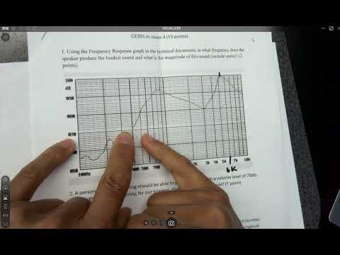
- The speaker response graph peaks at approximately 5.6 kHz, where its output is close to 100 dB.
- Using 70 dB as the hearing threshold on the plotted response, the lowest frequency meeting that level is roughly 400 Hz.
- The graph’s frequency divisions are approximately 200 Hz in the region around the peak, allowing the peak to be estimated between the 5 kHz and 6 kHz marks.
- The amplifier’s signal input is pin 4, labeled the inverting input; the board schematic routes the microcontroller signal to the amplifier input marked PRE.
- A capacitor in series with the signal forms a high-pass coupling stage that blocks DC offset while allowing the audio’s changing AC signal through.
- A capacitor from a signal node to ground forms a low-pass filter: it has little effect on DC but diverts more high-frequency signal toward ground.
- A DC offset does not change an audio signal’s oscillation frequency, but it can raise the baseline and contribute unwanted noise.
- The earlier music example uses Timer1 as the outer loop to set note duration and Timer3 as the faster inner loop to create the note’s oscillation.
- Timer3 uses a 1:1 prescaler for rapid toggling, while the longer-duration Timer1 configuration uses a divide-by-256 prescaler.
- Nested while loops become harder to manage when each note needs a different duration, motivating the interrupt-based approach in Tutorial 3.
- Without interrupts, code repeatedly polls the Timer1 overflow flag and clears it after detecting that the counter has wrapped.
- An overflow interrupt transfers execution to an interrupt service routine when the 16-bit counter rolls over, avoiding a dedicated polling loop.
- The ISR runs its handler and then returns to the point where the main program was interrupted, allowing timing events to be handled in the background.
- The Timer1 overflow flag is cleared automatically when the corresponding interrupt is serviced, so the ISR can trigger on a later overflow.
- The AVR overflow handler uses the fixed vector name TIMER1_OVF_vect, which the compiler associates with the Timer1 overflow interrupt address.
- Timer interrupts can also use output-compare match events, which trigger when a counter reaches a configured value rather than wrapping at 65,536.
- Input-capture interrupts can respond to an external signal, useful for detecting physical events without continuously checking a pin.
- Timer interrupt enables are controlled through the timer interrupt mask register, including the Timer1 overflow enable bit.
- The schematic labels two connections PRE; matching net names connect them on the PCB even when no wire is drawn between them.
- JP6 and JP5 provide jumper connections for routing the microcontroller’s PE3 output through the board’s low-pass filter toward the amplifier input.
- PE3 must be configured as an output if the program toggles it to generate notes; students can compare filtered and direct signal routing to assess audio quality.
- For a 1:1 Timer1 prescaler, set CS10, the least significant clock-select bit in TCCR1B.
- The bitwise expression TCCR1B |= (1 << CS10) sets CS10 without overwriting other TCCR1B settings.
- Enable Timer1 overflow interrupts by setting the overflow-enable bit in TIMSK1 using the same shift-and-OR technique.
- Reading a datasheet’s register bit definitions and applying bit masks are reusable skills, even for registers not previously covered in class.
- A local declaration such as static int counter = 0 initializes the counter once rather than resetting it every time the function runs.
- When the repeatedly called function increments and prints the static counter, its value persists across calls and continues increasing.
- Static variables are useful in loop-driven programs and interrupt service routines when a value must survive after a function returns.
Transcript excerpt
0:02 Okay, so tutorial three will be the material major material for today and there's the in class should be turning at the end of the class. Homework five is just all the tasks there are totally three tasks in tuto 3. Okay. And homework four is due Sunday this week. Any pressure on that? So the code was already covered here. Okay, so majority of the code is right here. Um, have you wrider worked on that? I know you already started working on it a little bit. Not yet. I forgot if I changed that line yet or not. Maybe Wednesday. I forgot. [clears throat]
0:48 Um, I could change it to Wednesday. Huh? No, I didn't change. Okay. So I I I think I recall that why they didn't change it because the majority of the code is already provided here right and then you put it in in your um IDE right ID and and debug it it shouldn't be very difficult because all the code is already given to you okay 99% uh maybe 90% of the code is already given to you here let's see if that works okay Sunday Um I'll change it to Monday. Okay. Monday. Monday midnight. Okay. Uh so so no lecture on Monday and Wednesday. Um I
1:36 will cover hopefully two tasks of tutorial three. So you can work on that one for the rest of the week and also early next week. Uh so come back on Friday. We will wrap up all the tasks. task number two part of the task number two and uh number three which is a little bit more challenging uh and then tutorial three will be done by Friday and then that's due the week after with the Wednesday after it so you should
This is the start of the transcript. Save this video free for the whole transcript, searchable and time-coded.
Related notes
Summary, takeaways, and chapters were generated by AI from the video's transcript and may contain errors. The video belongs to its creator, Yiyan Li.