CE351 lec11 Timer/counter, play single notes, play a song
 Watch on YouTube →
Overview
Yiyan Li explains AVR timer setup and polling through register masks, prescalers, overflow flags, and counter preload values, then applies the same ideas to generate notes and sequence a song. The song design separates pitch toggling with Timer3, note duration with Timer1, and the rest between notes with a delay function.
Key takeaways
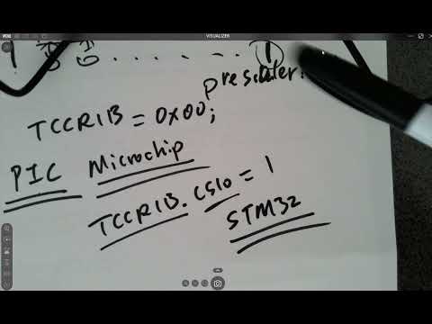
- On AVR, `TCCR1B |= (1 << CS10)` sets Timer1's CS10 bit without changing other control bits, selects a 1:1 prescaler, and starts the timer.
- Timer overflow flags provide a hardware-based timing event: poll TOV1 or TOV3 until it becomes 1, then clear the flag by writing 1 to that bit.
- For a 16-bit timer, preload the counter with 65,536 minus the required count total to produce a chosen overflow interval.
- Song playback requires three distinct timing mechanisms: Timer3 for pitch oscillation, Timer1 for note duration, and a delay function for rests between notes.
- The demonstrated button logic starts playback on release: wait for the active-low input to go low, then wait for it to return high.
Chapters
- AVR examples commonly set register bits with an OR mask such as TCCR1B |= (1 << CS10), leaving unrelated bits unchanged.
- CS10, CS11, and CS12 are the three clock-select bits in Timer1 control register TCCR1B; CS10 is bit 0.
- Setting CS10 alone selects a 1:1 prescaler and starts Timer1, so prescaler choice and timer activation happen together.
- Assigning 0 to TCCR1B stops Timer1 and clears its control settings.
- AVR code can configure individual bits with shifted masks, while other platforms may use different register-access conventions.
- Timer-specific register names must match the selected timer, for example, Timer0 uses TCCR0B rather than TCCR1B.
- The loop `while ((TIFR1 & (1 << TOV1)) == 0);` waits until Timer1's overflow flag becomes 1.
- TOV1 is set by the timer hardware when the counter overflows, so software can wait on a hardware-generated event instead of repeatedly comparing counter values.
- After overflow, the code stops Timer1, clears the overflow flag by writing a 1 to TOV1, and resets the counter for the next interval.
- A 16-bit timer counts through 2^16 values, or 65,536 states, before overflowing.
- Preloading the counter with 2^16 minus the desired number of counts sets the interval until overflow.
- After the timer period, the code can toggle the output and advance a note index; Yiyan Li emphasizes planning this control flow before writing code.
- A song needs separate timing for each pitch's fast oscillation, how long each note lasts, and the rest between notes.
- The button input is active low: wait while it is high, then wait for it to return high before starting playback on release.
- The example uses timers for pitch and note duration, while a delay function handles the gap between notes.
- Timer1 controls the longer note-length interval, with a larger prescaler such as 256 slowing the counter for a duration on the order of half a second.
- The counter preload is calculated as 2^16 minus the counts needed for the chosen note duration.
- While Timer1 has not overflowed, the program continues generating the current pitch; its overflow ends the note.
- Timer3 controls the faster half-period of the pitch; setting CS30 starts Timer3 with a 1:1 prescaler.
- The program waits for Timer3's TOV3 flag, stops the timer, clears the flag by writing 1, resets the counter, and toggles the speaker output to create each oscillation.
- Once Timer1 ends the note, the code stops and clears Timer1, inserts a delay between notes, and increments an index into a predefined song-note list.
- Each song-list entry maps to a defined note value and its corresponding half-period count.
Transcript excerpt
0:00 Okay. So these are the steps uh needed the steps needed to to run a timer. Okay. So these are the most important steps that you guys need to remember and even though different microller platforms may require different kind of stealth programming but for all these Arduino or AVR controllers let's just follow this pattern. This is very important. So when you guys are doing this I mean every different companies they have a different uh patterns or convention of programming but writing writing timers configuring all the bits let's just follow whatever the specific montour I usually use right as a convention so for Arduino for AVR montours the way we set up uh or configure bits is using a
0:50 number one so it's actually eight bit one it's all seven zeros with one at LSB and then we shift that one to the left for a certain number of steps in order to set or reset a certain bit and doing an end or or logic to achieve it. So that is why it looks so weird for this uh for this code for this piece of code here right this line it's actually just doing it's actually just doing u uh writing a one right writing a one to CS10 bit to that bit but it's doing it's making things looks very complicated maybe unnecessary but it's just a convention if you're looking at all the standard standard examples from AVR
1:37 mours they all use this pattern. Okay. So what's happening is they do uh one and shift left shift for this uh bit the name of the bit in the register. What is CS10 mean? What's that? What is that bit over there? Remember >> of the Chris Gator, right? The C or the the register. So that bit is one of the
This is the start of the transcript. Save this video free for the whole transcript, searchable and time-coded.
Related notes
Summary, takeaways, and chapters were generated by AI from the video's transcript and may contain errors. The video belongs to its creator, Yiyan Li.