EECS 373 - Fall 2026 - Lecture 15: "DACs"
Overview
The lecture compares practical digital-to-analog converter designs, from PWM with an RC filter to voltage-divider, R-2R, and binary-weighted resistor DACs, emphasizing trade-offs in speed, resolution, linearity, area, and power. It also explains output loading and buffering, DAC error types, and why a microcontroller DAC may need an external speaker driver or a dedicated audio DAC for demanding applications.
Key takeaways
- A DAC's output voltage can be corrupted by load resistance, capacitance, or inductance; a voltage buffer protects the DAC by supplying load current from a separate stage.
- PWM with an RC filter is a cheap way to make analog output from a GPIO pin, but its ripple and slow duty-cycle updates make it unsuitable for demanding waveform generation.
- Voltage-divider DACs switch quickly among ready-made voltage levels but need many resistors, while R-2R ladders reduce the required resistor values to a matched R-to-2R structure.
- Binary-weighted resistor DACs save circuit area by using fewer resistors, but mismatch can affect multiple codes and worsen linearity.
- Microcontroller DAC outputs are signal-level sources, not speaker drivers: a specified 5-kilohm load is fundamentally different from an 8-ohm speaker.
- Offset and full-scale errors are often calibratable, while differential nonlinearity can create missing or repeated steps that complicate signal processing and control.
Chapters
- Revised project proposals are due Friday and should be labeled as revisions in project folders so the changes from the first version are clear.
- Teams should investigate uncertain project components early, such as wireless modules, to estimate complexity before deadlines approach.
- Homework 7 is due Monday; the second midterm is scheduled for the following Friday, with practice exams and a data sheet review planned.
- Student technology presentations will run about 12 to 15 minutes, include peer feedback, and teach classmates about embedded hardware.
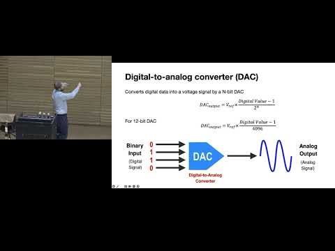
- A DAC converts digital codes into analog voltage values, which can be updated over time to approximate sine, square, triangle, or arbitrary waveforms.
- A microcontroller DAC may support output frequencies in the megahertz range, but typically only across a range near 0 to 3.3 volts.
- A bench function generator can offer a wider range, such as plus or minus 20 volts, while audio DACs are optimized for human hearing bands.
- Finite DAC source resistance and load resistance form a voltage divider, so the output can fall below its intended voltage under load.
- An 8-ohm speaker is a demanding load; a microcontroller DAC cannot directly supply the current needed to drive it.
- A voltage buffer presents a high-impedance input to the DAC and uses an op-amp to supply current to the load.
- Capacitive and inductive loads can also distort or slow output signals, even when their DC resistance seems manageable.
- A GPIO pin can produce PWM, and an RC low-pass filter smooths its high-frequency switching into an average analog voltage.
- Changing the PWM duty cycle changes the filtered output level; a piezoelectric buzzer can use this approach to produce tones.
- The filtered signal retains ripple from capacitor charging and discharging, and changing output levels is much slower than a dedicated DAC.
- A resistor ladder generates a set of voltage levels, and switches select which level appears at the output.
- The design is fast because each voltage is already available and output changes mainly require switching.
- As resolution increases, the circuit needs more resistors and switches, increasing silicon area and making resistor matching more difficult.
- Resistor mismatch changes individual voltage steps and can reduce the DAC's linearity.
- An op-amp summing amplifier adds currents from multiple input branches at a virtual-ground node.
- Changing the input voltages or branch resistances changes each current contribution, allowing several binary-controlled inputs to combine into one output.
- The illustrated summing topology produces an inverted output, but additional circuitry can provide the desired polarity.
- An R-2R ladder uses two resistor values, R and 2R, to generate current contributions in binary proportions such as one-half, one-quarter, and one-eighth.
- Switches route selected contributions into a summing amplifier, which combines them into the analog output.
- Using repeated resistor ratios is easier to manufacture than requiring many distinct resistor values, but resistor matching still affects accuracy.
- This architecture uses fewer switches than selecting among every voltage level in a full resistor-string ladder.
- A binary-weighted DAC assigns different resistor values to different bits, so each switched branch contributes a distinct binary-scaled current.
- It requires fewer resistors than the other discussed DAC structures, making it attractive when silicon area matters.
- A mismatch in a weighted resistor can affect multiple output codes, making manufacturing errors and linearity harder to control.
- The design is common in microcontrollers where compactness may matter more than high-precision analog output.
- DACs have quantization error because a finite digital code width can only represent discrete analog output steps.
- An output low-pass filter can smooth the stair-step waveform, but it also limits the highest usable output frequency.
- In direct digital synthesis and RF applications, DAC steps and nonlinearities can create unwanted spurious frequency components.
- For a given silicon area, binary-weighted designs can provide strong resolution because they use fewer resistors, though their resistor mismatch can impair linearity.
- A voltage-divider ladder can maintain consistent step sizes when its resistors are well matched, but its component count grows with resolution.
- The PWM-plus-RC method is inherently slower and noisier than the resistor-based DACs, despite requiring only a digital output and filter.
- The binary-weighted topology uses the fewest resistors and switches among the three resistor DACs discussed, while all resistor DACs can switch quickly.
- A microcontroller DAC is suitable for flexible general-purpose output, but high-fidelity audio may call for a dedicated audio DAC.
- Dedicated audio hardware can offer 24-bit resolution, audio-focused sampling rates, and smoothing filters; a microcontroller DAC may instead prioritize megahertz operation.
- For precision control applications, binary-weighted DAC nonlinearity may require calibration or compensation.
- The course device has two DACs, with full resolution available around 2 MHz and reduced resolution required for operation near 5 MHz.
- Its output buffer is specified for loads around 5 kilohms and 25 picofarads, which is far from the 8-ohm load of a typical speaker.
- Speaker playback requires a dedicated speaker-driver stage capable of supplying higher current; powered PC speakers are a practical option for loud project demonstrations.
- Offset error shifts the DAC's output steps by a roughly constant amount and can often be corrected through calibration.
- Full-scale error behaves like a gain error, causing output codes to diverge from ideal values across the range.
- Factory calibration may measure selected output points and store correction values in a lookup table, rather than testing every possible code.
- Differential nonlinearity changes the size of individual code steps; severe cases can produce repeated or missing output levels.
- Integrated error measures accumulated deviation from the ideal transfer curve and matters in high-accuracy DAC and ADC applications.
- Nonlinear converter errors can create spurious components in FFT-based signal analysis and may disrupt analog control loops.
- Practical systems should measure their noise floor and determine whether the least significant one, two, or three bits are reliable.
Transcript excerpt
0:00 All right. All right, we're going to get started. Let's see here. All right, so I talked to almost all of you. 30 groups is a lot. We saw some more group discussions to go through, but because we changed schedule around a little bit Project revisions are due on Friday. Please label your revised project proposal as revision so we can look at the delta between the first and the second. You're only really graded on the second and really the purpose of the project proposal is to force you to think through all the pieces of your project
0:50 and kind of get your head around the scope. The thing I want you all to think about in the like the next week or so is and maybe next two weeks is really you need to You have a very vague notion of some aspects of your project and you need to start getting line of sight on them and understanding how complicated they are. How does it really work? If you can't gauge how much work is ahead of you, you're in a lot of trouble. So if maybe you have lots of questions about how your wireless module is going to work and it feels like a opaque black box and it's horrible, right? Like it's just complete unknown. You don't know anything about RF, well start doing some research online, get the parts, go talk to James, go talk to me or the IAs and get that information so it's not overwhelming so you know like how much work is it going to take to get that done. I worry when there's unknowns in your mind and then you get to like a week
1:38 before the deadline and you just haven't even started it. That's usually a recipe
This is the start of the transcript. Save this video free for the whole transcript, searchable and time-coded.
In this course
Related notes
Summary, takeaways, and chapters were generated by AI from the video's transcript and may contain errors. The video belongs to its creator, Interactive Sensing and Computing Lab.