ECE 1230 F26 U2 L7 First Oder Examples
 Watch on YouTube →
Overview
Professor Angela Rasmussen reviews first-order circuit analysis for ECE 1230, working through a switched RC circuit and a switched RL circuit using initial value, final value, and time constant. The examples emphasize capacitor-voltage and inductor-current continuity, node-voltage analysis, source deactivation for finding Thevenin resistance, and the exponential response formula; the class ends by beginning a phasor-addition exercise.
Key takeaways
- A capacitor’s voltage is continuous through switching, so its t = 0+ model is a voltage source equal to its t = 0− voltage, not a short circuit.
- An inductor’s current is continuous through switching, so its t = 0+ model is a current source equal to its t = 0− current, not an open circuit.
- The standard first-order response is final value + (initial value − final value)e^(−t/τ); the exponential coefficient is found by subtracting the final value from the initial value.
- For capacitors, τ = RTHC; for inductors, τ = L/RTH. Find RTH by opening independent current sources, shorting independent voltage sources, and tracing the resistance seen at the energy-storage element’s terminals.
- Node voltage and component voltage drop are different quantities: use node-voltage KCL and subtract node potentials to obtain the voltage across a component or between two circuit locations.
- Add and subtract phasors in rectangular form, while multiplying and dividing them in polar form.
Chapters
- The first-order circuit quiz is due Friday night, with practice available in Unit 2 problems, prior Exam Two tests, and the ULIB book.
- Concept-quiz retakes are available until Tuesday night before the exam.
- Exam Two review topics include an RCL example, a sinusoid, and a phasor example.
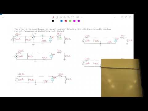
- At about 2:23, students begin solving a switched first-order circuit as practice for the upcoming quiz.
- The displayed circuit includes a 3 kΩ resistor, and a redrawn version is offered to make the topology easier to read.
- The class spends time attempting the switched-circuit problem before Angela Rasmussen works through the method at about 29:59.
- The later solution uses a 2 mF capacitor, resistor networks, and 18 V and 2 mA sources.
- Rasmussen explains that a voltage between nodes A and B is the difference VA minus VB, not either node voltage alone.
- For the RC problem, the first task is to analyze the circuit at t = 0− and determine the capacitor voltage that remains continuous at switching.
- A resistor is not ground: its voltage drop must be included when identifying a node voltage.
- Rasmussen warns that an 18 V source or a 2 mA current through a 2 kΩ resistor does not by itself set a nearby node to 18 V or −4 V.
- She labels unknown node voltages VA and VB, then writes resistor currents using Ohm’s law and applies KCL.
- The method distinguishes a component’s voltage drop from the voltage of a node relative to ground.
- The pre-switch analysis supplies the capacitor voltage used immediately after the switch moves.
- At t = 0+, the capacitor acts as a voltage source whose value is the voltage found at t = 0−; it does not become a short.
- The worked RC example uses −7 V as the capacitor’s initial voltage after switching.
- The current found in the pre-switch circuit is not automatically the post-switch initial current.
- Once the capacitor is modeled as its retained voltage source at t = 0+, the circuit must be re-solved for the desired current.
- The example obtains an initial I1 of 17/4 kΩ in the switched state.
- For t → ∞, the switch remains in position two and the capacitor is modeled as an open circuit.
- Rasmussen solves the resulting node-voltage network and obtains a final capacitor voltage of −9 V.
- The final value of I1 is 9/4 kΩ.
- For a capacitor, τ = RTHC; independent current sources are opened and independent voltage sources are shorted to find RTH.
- The resistance seen by the 2 mF capacitor is 2 kΩ, giving τ = 4 seconds.
- The capacitor response is −9 + [−7 − (−9)]e^(−t/4), and I1 approaches 9/4 kΩ from its initial value 17/4 kΩ.
- For an RL poll question with iL(0+) = 5 mA, final current 20 mA, and τ = 2 ms, the response uses final + (initial − final)e^(−t/τ).
- The correct expression therefore has a −15 mA exponential coefficient and a 2 ms time constant.
- Replacing the capacitor with a short at t = 0+ would incorrectly force its voltage to jump from −7 V to 0 V.
- The new RL circuit has a 2 mH inductor, with the switch initially in position one before moving to position two at t = 0.
- At t = 0−, the circuit is in steady state, so the inductor is modeled as a wire.
- Rasmussen chooses a ground reference and labels an unknown node voltage Vx to solve for the inductor current.
- The initial-state KCL equation includes Vx/8 kΩ, a 3 mA source, and Vx/4 kΩ.
- The solution gives Vx = −8 V and an inductor current of −2 mA in the chosen reference direction.
- At t = 0+, the inductor acts as a current source retaining that same −2 mA current.
- At t → ∞, the switch is in position two and the inductor returns to its steady-state wire model.
- KCL at node VA uses VA/4 kΩ, the 3 mA source, and (VA − 12 V)/2 kΩ.
- The final inductor current is 1 mA.
- To find RTH, Rasmussen opens the current source and shorts the voltage source, then traces the path between the inductor terminals.
- The 3 kΩ and 4 kΩ branches are outside the relevant path; the 4 kΩ and 2 kΩ resistors are in series.
- RTH is 6 kΩ, so a 2 mH inductor has τ = L/RTH = 1/3 μs.
- Using iL(0+) = −2 mA, iL(∞) = 1 mA, and τ = 1/3 μs, the response coefficient is initial minus final, or −3 mA.
- Rasmussen explains that another inductor variable can be found either from the circuit or from vL = L diL/dt.
- For the voltage calculation, she revisits the t = 0+ network and solves the unknown node voltage rather than reusing the pre-switch value.
- The final check gives V1 = 6∠30° and V2 = 6∠−30°.
- Rasmussen reviews that phasors must be converted to rectangular form for addition and subtraction; polar form is convenient for multiplication and division.
- The class starts the conversion but postpones completing the sum until the next session.
Transcript excerpt
0:00 All right, welcome. So, make sure that you take the quiz this week. So, quiz due by Friday night. It is a first order since that seemed to be the one that was a little bit more difficult. So, um, it will be a first order circuit that you'll have to solve similar to the other ones we've worked on. Okay. So, that's due by Friday night. So, make sure to take that when you're ready. Again, you can get practice problems through the unit 2 practice problems. There's examples from last year's test.
0:50 So, under exam two, there'll be um last year's test. There's three of them. And then there's some other ones from the past that are kind of down below that will be also have some of those types of circuits in there too. So those are all locations you should be able to find examples. And then the ULIB book will also have um the chapter problems will also have some other examples on there. So do practice those until you're very comfortable with them and then take the quiz again. um by next uh Tuesday night, you will have the option to do uh retakes for the concept quizzes.
1:43 So, those will be due um Tuesday night before the exam. So, if you want to retake any of the quizzes and get a higher score, you're welcome to attempt those and take those also. All right. So, again, we're going to go over kind of what's going to be on the exam, which will be an RCL example. You're going to have a sinosoid and then a phaser example. So, this will be the content of what will be on the next quiz. Any questions before we we jump into kind of problem solving? Okay, so let's jump right in. Go ahead
This is the start of the transcript. Save this video free for the whole transcript, searchable and time-coded.
Related notes
Summary, takeaways, and chapters were generated by AI from the video's transcript and may contain errors. The video belongs to its creator, University of Utah: Professor Angela Rasmussen.