ECE 1230 F26 U1 L7 Review Op Amps part 2
 Watch on YouTube →
Overview
Angela Rasmussen reviews op-amp resistor networks by identifying standard configurations and applying superposition. She derives a cascaded circuit output of Vout = 3V1 + 3V2 - 4V3, then outlines a design using a non-inverting summer and comparator with a 10 V threshold and ±15 V supplies. The design walkthrough contains a coefficient mismatch: the prompt requests 3V1 + 3V2, but the later resistor choice produces 3V1 + 2V2.
Key takeaways
- A non-inverting summer with equal input resistors and gain 6 produces 3V1 + 3V2 because each input is halved before the amplifier gain.
- The reviewed cascaded circuit has the overall relationship Vout = 3V1 + 3V2 - 4V3, with the -4 coefficient coming from a 4 kΩ-to-1 kΩ inverting path.
- Superposition checks a multi-input op-amp circuit by activating one input at a time, grounding the others, and adding the resulting output contributions.
- To obtain +15 V when V3 is below 10 V and -15 V when V3 is above 10 V, the comparator must compare a 10 V reference on its non-inverting input against V3 on its inverting input.
- A divider across +15 V produces 10 V when the resistor from the reference node to ground is twice the resistor from +15 V to the node, such as 4 kΩ below and 2 kΩ above.
- The final summer example does not match its stated target: its 3 kΩ and 2 kΩ input resistors with gain 5 create coefficients 3 and 2, rather than 3 and 3.
Chapters
- The opening audio through about 4:03 is fragmentary and contains no complete circuit derivation.
- The technical review begins at 4:03 with a resistor-network problem involving multiple op-amp stages.
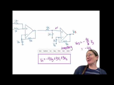
- The first stage is a non-inverting summer with gain 6; equal input resistors give each input a one-half contribution, producing 3V1 + 3V2.
- The second stage is a difference amplifier: its inverting path gives -4V3, while the first-stage output passes through a 4 kΩ and 1 kΩ divider.
- Combining the stage contributions gives Vout = 3V1 + 3V2 - 4V3.
- Rasmussen verifies the V1 and V2 terms separately by grounding the other inputs and tracing each non-inverting stage.
- With equal 1 kΩ input-divider resistors, each summing node receives half its input; subsequent gains and a 1:5 divider yield 3V1 and 3V2 at the output.
- Grounding V1 and V2 leaves an inverting amplifier for V3, with a 4 kΩ-to-1 kΩ feedback ratio and contribution -4V3.
- The exercise asks for an op-amp system that forms V3 = 3V1 + 3V2, then outputs +15 V below 10 V and -15 V above 10 V.
- A non-inverting summer is proposed for the weighted sum, followed by a comparator for the threshold decision.
- The class spends several minutes working on the design before Rasmussen begins the solution around 21:00.
- For the requested output polarity, the signal V3 goes to the comparator's inverting input and the 10 V reference to its non-inverting input.
- A divider from the +15 V supply can create 10 V using a 2 kΩ upper resistor and a 4 kΩ lower resistor.
- The walkthrough later selects 3 kΩ and 2 kΩ input resistors with a gain of 5, which yields 3V1 + 2V2, not the requested 3V1 + 3V2.
- The class was told there would be no quiz that weekend; students were encouraged to complete the Unit 1 practice problem before the exam.
Transcript excerpt
0:12 Hallelujah. It's not solved. be happy to
2:36 She's always even like I just All right. So on this you can solve just
4:07 by identifying what these are and then using the sets of equations that we've already solved for to match up the resistances correctly. >> So if you do it that way, you need to identify that the first one's a non-inverting sum and the second one is a difference or subtraction amp. In the non-inverting summer, >> it uses this resistor over this resistor plus one as your gain, which ends up being six here. And then your inputs each have a half because they're each equal. So it's going to be V2 over two and V1 over two. So that ends up being three. So this equals 3 V1
4:59 plus 3 V2. And then the next one is the difference amp. So in the difference amp it's this side's input V3 and then it's an inverting portion. So negative V3 * 4K over 1K. And then the output of the first op amp is before the divider of 4 4k and 1k. So that vx is 3 v1 plus 3v2 and then it gets divided down. So vx times 1k over the summation of both of those for 5k. So this ends up giving you the minus4 V3 + 3 V1 + 3 V2 total.
5:51 So I had done this as an exercise showing again you can do this for superp position. If I did just analyze this as each input that would then ground out the other inputs. So V1 comes in looks only like a non-inverting op amp. So this is non-inverting and this one is also non-inverting. And so the non-inverting is going to be 5k over 1k + 1 times the input. In this case, this
This is the start of the transcript. Save this video free for the whole transcript, searchable and time-coded.
Related notes
Summary, takeaways, and chapters were generated by AI from the video's transcript and may contain errors. The video belongs to its creator, University of Utah: Professor Angela Rasmussen.