ECE 1230 F26 U1 L7 Review Op Amps Part 3
 Watch on YouTube →
Overview
Angela Rasmussen reviews how to recognize inverting, non-inverting, and inverting-summer op-amp circuits, then applies their resistor ratios to a cascaded circuit. She corrects an initial unloaded voltage-divider assumption by accounting for the next stage’s 1 kΩ input path, yielding an overall output of 5V2 - 6V1, and designs a 10 kΩ-feedback inverting summer for -5V1 - 2V2.
Key takeaways
- An inverting amplifier’s gain is -RF/RS; 10 kΩ feedback and a 2 kΩ input resistor produce -5V2.
- A non-inverting amplifier’s gain is 1 + RF/R2; 6 kΩ feedback and 2 kΩ to ground produce an output of 4V1.
- An ideal op-amp with negative feedback holds its inverting input at the non-inverting input’s voltage, making a grounded non-inverting input a virtual ground at 0 V.
- A resistor divider cannot be treated as unloaded when the next circuit stage draws current; the 1 kΩ input path changes the intermediate node from the initially estimated 2V1 to V1.
- An inverting summer with 10 kΩ feedback and input resistors of 2 kΩ and 5 kΩ implements V3 = -5V1 - 2V2.
Chapters
- From 0:00 to about 9:35, the audio is mostly classroom setup and fragmented conversation.
- The substantive review begins around 9:35 with students identifying three op-amp configurations.
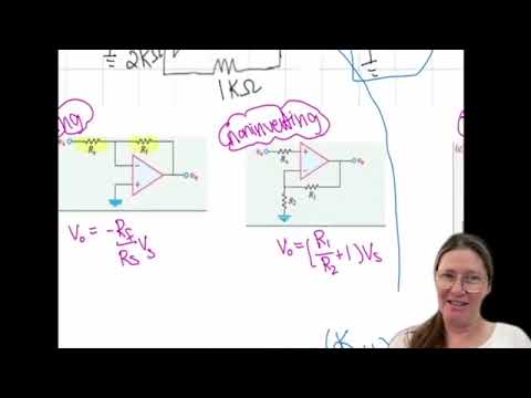
- The top-left circuit is an inverting amplifier, the bottom-left is a non-inverting amplifier, and the right-side circuit is an inverting summer.
- For the inverting stage, the 10 kΩ feedback resistor and 2 kΩ input resistor give a gain of -5, so its output is -5V2.
- For the non-inverting stage, 1 + 6 kΩ/2 kΩ gives a gain of 4, so its output is 4V1.
- The 7 kΩ resistor in parallel with the driven output node does not change that stage’s output voltage.
- The initial calculation treats two 2 kΩ resistors as an unloaded divider from 4V1, producing an intermediate voltage of 2V1.
- That divider assumption misses current through the following stage’s 1 kΩ input branch, so the intermediate node must be found using node-voltage analysis.
- Using the ideal op-amp virtual-ground condition, the inverting input connected to ground is at 0 V; the corrected intermediate voltage is V1.
- With a 6 kΩ feedback resistor and inputs of -5V2 through 6 kΩ and V1 through 1 kΩ, the corrected output is 5V2 - 6V1, not the initial 5V2 - 12V1.
- At about 22:07, the design task is to produce V3 = -5V1 - 2V2 using op-amps.
- An inverting summer matches the target because each input’s coefficient is the negative ratio of the shared feedback resistor to that input’s branch resistor.
- The two input branches need different resistor ratios to produce the coefficients -5 and -2.
- Choose a 10 kΩ feedback resistor for the inverting summer.
- Connect V1 through 2 kΩ to obtain a gain of -10 kΩ/2 kΩ = -5.
- Connect V2 through 5 kΩ to obtain a gain of -10 kΩ/5 kΩ = -2.
- The resulting output is V3 = -5V1 - 2V2.
Transcript excerpt
0:50 All right. All right. Oh my god.
2:15 Hello. You can
4:43 Oh, no. Me too. figure out a There's
5:49 something It's okay. And you
7:00 call So this is
8:14 I don't know. Oh, she just put those So
9:35 All right. So hopefully you were able to identify inverting amp on the top left. non-inverting amp bottom left >> inverting summer >> for the right side one. >> Everybody able to identify those? >> Yes. Okay, good. All right. Then I just wrote the equations for the inverting, non-inverting, and inverting summer from the um table that I gave you. You can drive these again if you want, but easier just to have them written out. So from here, you need to identify which resistors match up with the equations.
10:22 So in this one, it's that >> this resistor on the feedback portion. So RF over the RS. So for inverting one that's going to be 10K over 2K and it's negative. So -10K over 2K which equals minus 5 V2. So that first one should have an output at that node where it's marked as minus 5 V2. We can ignore the 7K because that's basically in parallel with this which we're treating like an a voltage source. So it doesn't that 7k doesn't change anything right because we set the node to the value of
11:10 the op amp. So that node becomes basically like a voltage source with the value of minus 5 v2. So then that goes into the 6k and into this the next portion the bottom side here again this node will act like a voltage source once I've determined it non-inverting for the non-inverting it's that feedback resistor over R2 + one so in this case that feedback resistor is 6k over 2k so 6k over 2k + 1
This is the start of the transcript. Save this video free for the whole transcript, searchable and time-coded.
Related notes
Summary, takeaways, and chapters were generated by AI from the video's transcript and may contain errors. The video belongs to its creator, University of Utah: Professor Angela Rasmussen.