ECE 1230 F26 U2 L1 Capacitors Inductors First Order Solutions
 Watch on YouTube →
Overview
Angela Rasmussen introduces capacitor and inductor behavior, then shows how first-order circuit responses can be solved from initial value, final value, and time constant rather than by repeatedly solving differential equations. The lecture applies the method to an RC circuit with a 33.325 ms time constant and demonstrates RC and RL responses in EveryCircuit, including the three-time-constant rule for reaching about 95% of steady state.
Key takeaways
- A capacitor's voltage is continuous across an ideal switch change, while its current may change immediately; at DC steady state, the capacitor acts as an open circuit.
- An inductor's current is continuous across an ideal switch change, while its voltage may change immediately; at DC steady state, the inductor acts as a short circuit.
- First-order circuit responses can be calculated with x(t) = x_final + (x_initial − x_final)e^(−t/τ), once the initial value, final value, and time constant are known.
- Use τ = R_thC for a capacitor and τ = L/R_th for an inductor, finding R_th at the reactive element's terminals in the post-switch configuration.
- Three time constants correspond to roughly 95% completion of a first-order transition, a practical rule for estimating settling time and designing circuit timing.
- The EveryCircuit examples verify the rules numerically: a 2 kΩ and 1 mF RC circuit has τ = 2 s, while a 0.2 H and 100 Ω RL circuit has τ = 2 ms.
Chapters
- Students locate the Unit 2 notes, titled U2 L1 Capacitors Inductors, in the course modules.
- The lecture shifts from the DC sources, resistors, op amps, and diodes covered in ECE 1220 to time-dependent capacitors and inductors.
- Complex-number and phasor handouts are also listed as learning materials for later use.
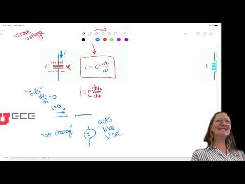
- A capacitor uses two conductive plates separated by an insulating material such as air or another dielectric.
- Separated charge creates a voltage difference, so the capacitor can store electrical energy and retain a voltage.
- The governing relation is i_C = C·dv_C/dt: current flows when capacitor voltage changes.
- Rasmussen describes an inductor as storing current and compares its response to a water wheel that takes time to get moving.
- The inductor law is v_L = L·di_L/dt, so a constant current produces zero voltage across an ideal inductor.
- A transient is the interval following a circuit change; steady state is the condition reached after the circuit has settled.
- In DC steady state, a capacitor behaves as an open circuit and an inductor behaves as a short circuit.
- Capacitor voltage cannot jump instantaneously, but capacitor current can change in response to the surrounding circuit.
- Inductor current cannot jump instantaneously, but inductor voltage can change; the stored state is carried across the switch event.
- For a resistor-capacitor circuit, the capacitor current is written as i_C = C·dv_C/dt.
- Applying current summation at the capacitor node gives a first-order differential equation involving R, C, the input current, and v_C.
- Solving by separation of variables leads to an exponential response, but Rasmussen notes that the method is cumbersome to repeat for every circuit.
- A first-order response transitions exponentially between an initial value and a final value.
- For a simple RC circuit, the time constant is τ = RC; it determines how quickly the capacitor voltage changes.
- After one time constant, a rising response has completed about 63% of its total change, while a decaying response has fallen about 63% from its starting value.
- Capacitors in parallel add directly, while capacitors in series combine using 1/C_eq = 1/C_1 + 1/C_2 + ….
- Inductors in series add directly, while inductors in parallel combine using 1/L_eq = 1/L_1 + 1/L_2 + ….
- The capacitor combination rules mirror resistors in parallel and series, respectively; ideal inductors follow the resistor combination pattern.
- The general response is x(t) = x_final + (x_initial − x_final)e^(−t/τ).
- For capacitor circuits, solve for v_C(t) and use τ = R_thC; for inductor circuits, solve for i_L(t) and use τ = L/R_th.
- Find R_th from the element's terminals by removing the capacitor or inductor, placing terminals A and B there, and deactivating independent sources.
- The solution requires the initial value at 0+, the final steady-state value at t = ∞, and the time constant τ.
- Use capacitor-voltage continuity or inductor-current continuity to transfer the state from just before the switch to just after it.
- Determine τ using the circuit in its post-switch configuration, because that configuration controls the response toward the final value.
- Before the switch closes, the circuit has been in steady state, so the capacitor is modeled as an open circuit and the switch remains open.
- Using the 16 V source and the resistor network, node analysis gives a capacitor voltage of 12 V at 0−.
- Because capacitor voltage is continuous, v_C(0+) is also 12 V, which becomes the example's initial condition.
- With the switch closed and the circuit settled, the capacitor is again an open circuit; the resulting resistor network gives a final capacitor voltage of 10.7 V.
- For τ, the capacitor is removed and the resistance seen at its terminals is found in the final switch position.
- R_th = 1.33 kΩ and C = 25 μF produce τ = R_thC = 33.325 ms.
- The example capacitor voltage decays exponentially from 12 V toward 10.7 V after the switch changes.
- One time constant marks 63% of the total transition; about three time constants reach roughly 95% of the final value.
- For a design target of settling in 1 second, Rasmussen recommends setting approximately 3τ = 1 second, or using 3τ to 4τ for a more conservative estimate.
- Rasmussen introduces EveryCircuit as a simpler circuit simulator than LTspice, useful for visualizing current flow and stored charge.
- Students can use the EveryCircuit app or everycircuit.com; the free version limits circuit complexity, and purchasing it is not required.
- The class completes a survey and prepares to build circuits by dragging components, rotating resistors, wiring nodes, and editing component values.
- Students build a 10 V source, 2 kΩ resistor, switch, and 1 mF capacitor in EveryCircuit, giving τ = 2 seconds.
- The capacitor reaches about 6.28 V after 2 seconds, approximately 63% of the 10 V change.
- At 4 seconds the voltage is about 8.5 V, and at 6 seconds it is about 9.5 V, demonstrating that three time constants approach 95% of steady state.
- The RL demonstration uses a 1 V source, 100 Ω resistor, and 0.2 H inductor, giving τ = L/R = 2 ms.
- Students track inductor current, which rises toward the 10 mA steady-state value; at one time constant it has completed about 63% of that change.
- Rasmussen recommends bringing a computer or iPad for future simulations; there is no weekly quiz this week, and students can begin with Unit 1 practice problems.
Transcript excerpt
0:13 Okay. So it should notes should be under this unit two professors inductors first order solutions and then this unit two. So refresh your pages if you aren't seeing that. It should pull up. And then under this learning material um we're going to talk about um complex and so what's called a phaser. So this is some more information once we get in these handouts are more about the math side of it. [snorts] And then the notes is this U2 L1 capacitors inductors. Are you guys finding it that have
1:01 >> still? No. >> So maybe close your app and then restart. It should be in there. So one person has gotten it. Anybody else access still? No, you got it too. Okay. show.
2:23 Yeah. So if you click on it from the homepage, it looks like it takes you down further in the modules list. Just scroll up to that unit, too. So it's before the attendance after exam one. You found it.
3:51 >> All right. Seems like some of you are getting it. It just taking a minute to kind of updating, I guess. So as that's going hopefully you can access those notes and if not then you guys can just hopefully I have something to write on. Um so so far we've um so in 1220 you learned all about the um DC component so current source voltage source resistors. Um you also learned a little bit about opamps and diodes. Um but what we're going to move now is like a resistor is called a it's a linear device. You put in voltage and you get out a linear graph of as I change my voltage my current goes up and
4:40 I can graph it linearly. So that's called a linear element. it is DC. I mean you can put AC signals
This is the start of the transcript. Save this video free for the whole transcript, searchable and time-coded.
Related notes
Summary, takeaways, and chapters were generated by AI from the video's transcript and may contain errors. The video belongs to its creator, University of Utah: Professor Angela Rasmussen.