ECE 1230 F26 U2 L2 Capacitors Inductors First Order Solutions Part 2
 Watch on YouTube →
Overview
Angela Rasmussen teaches a four-state method for solving first-order capacitor and inductor circuits: find the pre-switch steady state, the continuous storage-variable value at 0+, the post-switch final state, and the time constant. Worked examples apply the general response equation to an inductor circuit with a 0.375 A final current and 0.1 ms time constant, and a capacitor circuit changing from 10 V to 6 V with a 240 ms time constant.
Key takeaways
- A first-order response can be assembled from four results: the pre-switch steady state, the continuous storage-variable value at 0+, the post-switch final state, and τ.
- Capacitor voltage and inductor current cannot change instantaneously; preserve the corresponding pre-switch value when modeling the transient at 0+.
- At steady state, a capacitor behaves as an open circuit and an inductor as a short circuit; during the switching instant, use an equivalent voltage source for a capacitor or current source for an inductor.
- After one time constant, a first-order response has covered about 63% of the distance to its final value; after three time constants it is close enough to the final value for many design estimates.
- For the inductor example, L = 3 mH and R_th = 30 Ω give τ = 0.1 ms, while the circuit’s current rises from 0 A to 0.375 A.
- For the capacitor example, C = 2 mF and R_th = 120 Ω give τ = 240 ms, and the voltage response moves from 10 V toward 6 V.
Chapters
- The Unit 2 Quiz 1, due Friday, covers first-order analysis and requires identifying circuit components and forming the response equation.
- Angela Rasmussen’s four-state method finds a variable before switching, at the switch event, at the final state, and the time constant.
- Capacitor voltage is continuous across the switch event, while inductor current is continuous.
- The response is x(t) = x_final + (x_initial - x_final)e^(-t/τ).
- For a capacitor, τ = RC; for an inductor, τ = L/R_th.
- The method applies to a circuit with one capacitor or one inductor and otherwise resistive elements.
- Use i_C = C·dv_C/dt to see that a capacitor is an open circuit at steady state, when its voltage is no longer changing.
- Use v_L = L·di_L/dt to see that an inductor is a short circuit at steady state, when its current is no longer changing.
- At the switching instant, model the capacitor as a voltage source and the inductor as a current source, preserving their pre-switch voltage or current.
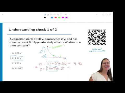
- For a capacitor moving from 10 V toward a 2 V final value, the total change is 8 V.
- After one time constant, the response has completed about 63% of the change, leaving about 37% of the initial-to-final difference.
- The resulting voltage is approximately 2 V + 0.37(8 V) = 4.96 V, so 4.9 V is the closest listed choice.
- The time constant sets the response’s speed, not the final voltage or current.
- After one τ, a first-order response has moved about 63% toward its final value; about 37% of the original difference remains.
- Charging and discharging speed depends on the circuit connected when a switch changes position.
- Three time constants are used as a practical rule of thumb for treating a first-order response as nearly settled.
- For a desired timing interval of 1 second, the design target is approximately 3τ = 1 second.
- For an RC circuit, choose a practical capacitor and then select a resistor so their product gives the required τ.
- An RC time constant can control pulse timing or triggering, including in a 555 timer circuit used in lab.
- Changing the capacitor changes the timing because τ = RC.
- Inductors oppose abrupt changes in current, so current ramps up or down after a circuit change rather than changing instantaneously.
- Start by stating whether the switch changes from open to closed or from closed to open at t = 0.
- For an open-to-closed event, the pre-switch circuit is open and has been in steady state for a long time.
- The worked example seeks inductor current first; inductor voltage can then be found using v_L = L·di_L/dt.
- At 0−, draw the switch in its pre-event position and replace steady-state inductors with shorts and capacitors with opens.
- At 0+, put the switch in its new position and replace an inductor with a current source equal to its 0− current, or a capacitor with a voltage source equal to its 0− voltage.
- At the final state, keep the new switch position and again use the steady-state short model for an inductor or open model for a capacitor.
- To find an inductor’s time constant, remove the inductor, deactivate independent sources, and find R_th looking into its terminals.
- A voltage source becomes a wire when deactivated; the resulting R_th is used in τ = L/R_th.
- Do not confuse the transient source models at 0+ with steady-state open- and short-circuit models.
- With the switch initially open and no source-driven path, the worked circuit has i_L(0−) = 0 A.
- Inductor-current continuity gives i_L(0+) = 0 A, represented by a 0 A current source in the transient circuit.
- The initial current comes from the pre-switch analysis and is carried directly into the response equation.
- With the switch closed in the final circuit, node-voltage analysis gives approximately 0.375 A through the inductor branch.
- For the node calculation, Rasmussen labels the node V_x and applies Kirchhoff’s current law to the resistor branches.
- This 0.375 A is the final value used in the first-order current response.
- The resistance seen at the inductor terminals is 30 Ω, found by combining R1 and R2 in parallel and adding R3.
- With L = 3 mH, τ = L/R_th = 0.003/30 s = 0.1 ms.
- Using i_L(0+) = 0 A and i_L(∞) = 0.375 A gives i_L(t) = 0.375(1 - e^(-t/0.1 ms)) A.
- Analyzing only the post-switch circuit cannot provide every quantity needed for the response.
- A complete solution needs the pre-switch steady state, continuity at 0+, the post-switch final state, and the resistance seen by the storage element.
- The final value is not automatically zero, and capacitor-open or inductor-short models apply to steady state, not every transient condition.
- For a switch closing at t = 0, teams divide the work among finding the initial voltage, final voltage, R_th, and time constant.
- The goal is to combine those results into v_C(t) using the general first-order response equation.
- The capacitor voltage at 0+ must match the voltage found just before switching.
- With the switch initially open, no current flows through the relevant 300 Ω path, so the capacitor’s initial voltage is 10 V.
- After the switch closes, solving the final-state circuit with 200 Ω and 300 Ω branches gives v_C(∞) = 6 V.
- The capacitor sees R_th = 200 Ω || 300 Ω = 120 Ω; with C = 2 mF, τ = 240 ms.
- The resulting capacitor response is v_C(t) = 6 + 4e^(-t/240 ms) V; the 300 Ω current changes from 1/30 A initially to 1/50 A finally.
Transcript excerpt
0:02 All right, welcome. Any questions about the material up to this up to what we're covering today? So, capacitors, inductors, any questions so far? All right. So due by this Friday is your unit one or unit two quiz one which is on a first order analysis. So you will need to be able to look at the circuit figure out each of the components in there and write it in the general form. solution.
0:50 So each of those steps you'll need to be able to to go through. All right. So in order to do that, I kind of call this the four state method. So in this state or in these states, you need to find the variable you want at different time frames. So this is when you're looking at a switch in the circuit. No worries. You're looking at the switch in the circuit and the switch is going to be in different positions at different times. So I call the time before a change. I denote that as 0 minus time at right at the change
1:40 I call that a zero plus. And then at the final state I use kind of an infinite time. So those are the three kind of states that the switch would be in. So to do the four state method, you're going to find your variable at the time right before the change. If it's a capacitor, that's going to stay the same value before and after. So capacitor voltage stays the same. It can't instantaneously change where the current can. And for an inductor, your current is what stays the same before and after. So finding it at this is the first time.
2:31 The second time is using this information to then solve for the variable right at
This is the start of the transcript. Save this video free for the whole transcript, searchable and time-coded.
Related notes
Summary, takeaways, and chapters were generated by AI from the video's transcript and may contain errors. The video belongs to its creator, University of Utah: Professor Angela Rasmussen.