ECE 1230 F26 U2 L6 First Order and Sinusoid Examples
 Watch on YouTube →
Overview
Professor Angela Rasmussen prepares ECE 1230 students for Exam 2 by working through first-order RC and RL responses, sinusoid interpretation, and phasor operations. The lesson emphasizes steady-state and transient models, continuity of capacitor voltage and inductor current, Thevenin resistance and time constants, then applies those ideas to circuits and a 3 + cos(34.9t) waveform.
Key takeaways
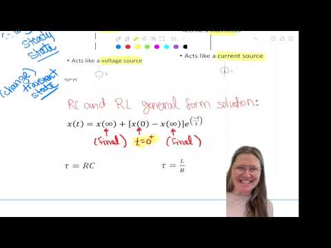
- For a first-order RC or RL response, use final + (initial − final)e^(−t/τ), with τ = RthC for a capacitor and τ = L/Rth for an inductor.
- Capacitor voltage and inductor current are continuous through switching; find them from the 0− steady-state circuit and use those values at 0+.
- In the worked RC example, 12 V initial, 36 V final, Rth = 6 kΩ, and C = 200 µF produce τ = 1.2 s and vC(t) = 36 − 24e^(−t/1.2).
- In the worked RL example, an 80 mH inductor with Rth = 40 Ω has a 2 ms time constant; its current changes from −10 mA initially to 20 mA at final steady state.
- For a plotted sinusoid, find amplitude from half the peak-to-peak range, DC offset from the centerline, and angular frequency from ω = 2π/T; five cycles in 0.9 s give about 34.9 rad/s.
- Phase requires a reference signal: compare corresponding points to find Δt, then calculate φ = (2π/T)Δt; positive phase leads and negative phase lags.
Chapters
- Exam 2 is scheduled for October 28 and includes an RC problem, an RL problem, and sinusoid analysis.
- For a plotted sinusoid, students must identify DC offset, amplitude, and frequency; calculating phase is not required, but leading and lagging must be understood.
- The phasor problem requires converting a sinusoid to a phasor, manipulating complex values, and converting the result back to the time domain.
- A first-order circuit has one energy-storage element, a capacitor or an inductor, and its response follows one exponential.
- The capacitor relation is i = C dv/dt, while the inductor relation is v = L di/dt.
- These element laws also explain the steady-state models and continuity rules used in circuits with multiple storage elements.
- After a long time under DC conditions, a capacitor has zero current and acts as an open circuit; an inductor has zero voltage and acts as a short circuit.
- At a switch transition, capacitor voltage and inductor current cannot change instantaneously.
- Use the 0− circuit to find the stored capacitor voltage or inductor current, then carry that value into the 0+ circuit; other voltages and currents may change immediately.
- The first-order response has the form final value + (initial value − final value)e^(−t/τ).
- For an RC circuit, τ = RthC; for an RL circuit, τ = L/Rth.
- Find Rth as seen from the storage element's terminals with independent sources deactivated, then use the final circuit configuration.
- The practice response has an initial value of 12, a final value of 36, and a time constant of 1.2 seconds.
- Substituting into the standard form gives 36 + (12 − 36)e^(−t/1.2), or 36 − 24e^(−t/1.2).
- The order matters: the standalone term is the final value, and the coefficient of the exponential is initial minus final.
- The RC exercise asks for initial and final values, Rth, the time constant, and the response expression.
- Analyze the first switch position at 0−, the new circuit at 0+, and the final circuit after a long time.
- The worked example uses a 200 µF capacitor and illustrates why neither the initial nor final capacitor voltage should be assumed to be zero.
- Before switching, the capacitor is at steady state and acts as an open circuit; a 4 mA current through 3 kΩ sets its voltage to 12 V.
- The capacitor voltage remains 12 V at 0+, even though other node voltages can change when the switch moves.
- In the pre-switch circuit, the separate node voltage VX is 36 V; after switching, the capacitor's fixed 12 V changes the circuit conditions.
- In the final switch position, the capacitor again acts as an open circuit, and 6 mA through 6 kΩ gives a final capacitor voltage of 36 V.
- Deactivate the independent current sources to find the resistance seen by the capacitor; the example gives Rth = 6 kΩ.
- With C = 200 µF, τ = RthC = 1.2 s, so the capacitor response is 36 + (12 − 36)e^(−t/1.2).
- For current I2 through the 2 kΩ branch, the final value is 6 mA and the initial value is 2 mA, giving I2(t) = 6 mA + (2 − 6)mA e^(−t/1.2).
- Every voltage and current in this first-order circuit shares the capacitor's 1.2-second time constant.
- Capacitor current can be found from iC = C dvC/dt or from the circuit; its final steady-state value is zero.
- Students work through a switched RL circuit using the same sequence of pre-switch, immediate post-switch, and final-state analyses.
- For an inductor, preserve current across the switching instant and model the inductor as a short in steady state.
- The exercise also asks for an expression for I2, the current through the 40 Ω branch.
- The inductor's pre-switch current is −10 mA; after switching, its current remains −10 mA while the transient I2 current is 30 mA.
- At final steady state, 20 mA flows through the inductor and I2 through the 40 Ω resistor is zero.
- The resistance seen by the inductor is 40 Ω, so L/Rth gives τ = 2 ms; the same time constant applies to I2.
- To write a sinusoidal expression from a graph, identify the centerline as the DC offset and calculate amplitude as half the peak-to-peak value.
- The example graph has a centerline of 3 and peak-to-peak amplitude 2, so its sinusoidal amplitude is 1.
- For frequency, measure a clear interval spanning several cycles rather than estimating the spacing between indistinct peaks.
- The graph shows five cycles across 0.9 s, so the period is 0.9/5 = 0.18 s and frequency is 1/T.
- Convert frequency to angular frequency using ω = 2πf, yielding approximately 34.9 rad/s.
- Combining the DC offset, amplitude, and angular frequency gives 3 + cos(34.9t); the initial spoken calculation is corrected after a student points out the reciprocal.
- A phase shift cannot be determined from one sinusoid alone; it compares one signal with a reference, such as the circuit input.
- The time displacement Δt between corresponding points converts to phase using φ = (2π/T)Δt.
- A positive phase indicates a leading signal and a negative phase indicates a lagging signal; the blue waveform in the illustrated comparison lags.
- In 2.5 + 5 cos(42t), the DC component is 2.5 and the sinusoidal amplitude is 5.
- Because the coefficient of t is written as ω, 42 is in radians per second by default; a value in hertz must be labeled accordingly.
- The expression includes a DC offset, so a description that treats it as a zero-centered cosine is incorrect.
- A free circuit-simulation version can demonstrate the RC response, but its component limit may require replacing the pre-switch circuit with an equivalent voltage or current source.
- The classroom example uses a 200 µF capacitor and a 1.2 s time constant; the plotted response moves between 36 V and 12 V.
- The time constant is the same for charging and discharging, so either direction can be used to verify it.
- For additional preparation, Rasmussen recommends the Unit 2 practice problems, ULiB RC and RL exercises, and three prior-year Exam 2 versions.
Transcript excerpt
0:06 All right. So, kind of getting back into school after the break. Um, any questions from any of the material up to now? Anybody have any questions? Okay. Um, so we're going to just be going over problems and problems and problems um to prepare you for this next exam. I find that this exam the students struggle the most on the first order solution for some reason. Um, so we'll try and do quite a few of those examples and your next quiz will also be another first order example or first order problem. Is the next exam next week?
0:55 >> Uhhuh. Yeah. So the exam I think it's on the 28th if I remember correctly. >> Yeah. >> So a week from Wednesday will be your next exam. So exam two October 28th. Okay. So on that there'll be an RC circuit. So this will be your problems. I'll just tell you frankly what they will be. You have an RC problem. You'll have an RL problem. [snorts] And then you're going to have a sinosoid where you're going to have the graph and you're going to have to write the expression for it determining the frequency in it. Um if there's a DC offset and the amplitude. So and the
1:44 phase if there's a phase shift. Um the phase shift I won't make you calculate because sometimes that's more complicated. Um so it will just be the frequency only. So finding the three values DC value, amplitude and frequency of those. >> So notation. >> Yeah. So um I want you to understand the concept of being able to know like is that leading or lagging but not necessarily the calculation of it. >> So we don't have a solid You just have to understand. >> You just have to understand phase shift.
This is the start of the transcript. Save this video free for the whole transcript, searchable and time-coded.
Related notes
Summary, takeaways, and chapters were generated by AI from the video's transcript and may contain errors. The video belongs to its creator, University of Utah: Professor Angela Rasmussen.