ECE 1230 F26 U2 L3 First Order Sinusoids
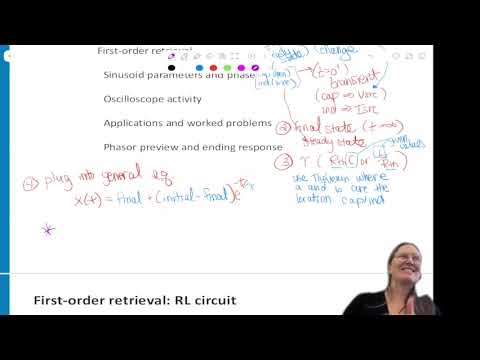 Watch on YouTube →
Overview
Professor Angela Rasmussen reviews the first-order RC/RL analysis workflow, including switch-time initial conditions, steady-state limits, Thevenin resistance, and the exponential response, then introduces sinusoidal amplitude, frequency, and phase. A switched RL example and a measured-waveform exercise connect the methods to practical quiz problems and applications such as audio, radio, power systems, and noise-cancelling headphones.
Key takeaways
- A first-order RC or RL response is determined by three quantities: the stored-energy initial value at 0+, the final steady-state value at infinity, and the time constant τ.
- For an RC circuit τ = RTHC, while for an RL circuit τ = L/RTH; RTH is found looking into the energy-storage element’s terminals after deactivating independent sources.
- After one time constant, a first-order response has completed about 63% of its total change; after three time constants, it is approximately 95% complete.
- A sinusoid’s amplitude is half its peak-to-peak value, its period gives f = 1/T, and its angular frequency is ω = 2πf; phase must be stated relative to a reference signal.
- Leading and lagging describe when a waveform occurs relative to its reference: an earlier waveform leads, and a later waveform lags.
- A phase difference of 180 degrees inverts a signal, a principle used by noise-cancelling headphones to oppose incoming sound.
Chapters
- Quiz 1 is due Friday night and requires a complete RC or RL analysis, including an expression for capacitor voltage or inductor current.
- Students must evaluate the response at a specified time, such as 1 microsecond or 1 millisecond, and enter the result in Canvas.
- Practice is available in Unit 1 problems, the ULIB, and solutions to earlier quizzes on Canvas.
- Use the circuit just before switching, at 0−, to find the stored capacitor voltage or inductor current after a long-time steady state.
- At 0+, capacitor voltage and inductor current cannot change instantaneously, so their 0− values set their initial conditions.
- For DC steady state, model a capacitor as an open circuit and an inductor as a wire; in the transient model, represent them with a voltage source and a current source, respectively.
- Find the final value at t = infinity using the post-switch circuit in steady state, then calculate the time constant.
- For an RC circuit, τ = RTHC; for an RL circuit, τ = L/RTH, where RTH is found looking into the capacitor or inductor terminals with independent sources deactivated.
- Use x(t) = xfinal + (xinitial − xfinal)e^(−t/τ) for circuit voltages and currents; all variables in a first-order circuit share the same time constant.
- The exponential form results from solving the circuit differential equation, which follows from capacitor and inductor voltage-current relationships.
- Rasmussen introduces an RL circuit driven by a Thevenin-equivalent source and asks students to find the inductor-current response.
- The switch changes from open to closed at t = 0, so students first analyze the open-switch, pre-change circuit.
- For each time interval, identify the switch position and whether the inductor is in steady state or transient operation.
- Students work through the switched RL example by distinguishing the pre-switch condition, the 0+ transient, and the final steady state.
- The key modeling decision is whether the inductor is a wire or a current source; its current-source value comes from the current immediately before switching.
- The class discussion focuses on applying the same initial-condition rules to the circuit even when other voltages and currents change at the switch.
- Before the switch closes, the source-free circuit has zero inductor current; at 0+, the inductor is modeled as a zero-amp current source.
- For a separate resistor-current calculation, the post-switch transient value is derived as 10/800 A, or 1/80 A; the final steady-state current is 10/500 A, or 1/50 A.
- With the independent voltage source shorted and the inductor removed, the resistance seen is 500 Ω in parallel with 300 Ω; τ = L/RTH is reported as 32 microseconds.
- Substitute the initial value, final value, and 32-microsecond time constant into the exponential response to obtain the time-dependent current.
- Quiz 1 permits course notes and course materials but prohibits AI tools, Yubot, and internet searches, including AI-powered search engines.
- An optional retake gives students a chance to use the quiz as practice before the next exam.
- Rasmussen encourages honest self-assessment so students can identify what needs more practice.
- For a capacitor starting at 0 V and approaching 12 V with τ = 2 ms, the response is 12 + (0 − 12)e^(−t/τ).
- After one time constant, the capacitor has completed about 63% of the change toward its final value, not reached 12 V.
- After approximately three time constants, the response is about 95% of the way to its final value.
- A sinusoidal signal can be represented as a DC offset plus an oscillating term with amplitude, angular frequency, time, and phase.
- The DC offset shifts the waveform’s centerline; amplitude is half the peak-to-peak value.
- Angular frequency ω is conventionally in radians per second and phase is in radians; label frequency in hertz or phase in degrees explicitly when using those units.
- Measure the period T between repeating waveform features, then calculate frequency f = 1/T and angular frequency ω = 2πf.
- An oscilloscope can display a waveform’s measurements, but understanding how to derive the parameters is important for later circuit analysis.
- Phase is measured relative to a reference signal, usually the input, rather than assigned meaning from a waveform in isolation.
- A signal that reaches a corresponding point earlier than its reference leads it; a signal that reaches it later lags it.
- The green waveform serves as the reference in the comparison, with the earlier green-relative waveform leading and the later one lagging.
- The same terminology applies when comparing circuit quantities such as output voltage or current against an input.
- The worked oscilloscope example uses amplitude 4 and identifies sine waves because the reference waveform crosses zero at the origin; the waves initially move downward, so the expressions use a negative amplitude.
- Rasmussen reports an angular frequency of 8,000 rad/s and computes relative phase shifts from measured time differences.
- With V1 as the reference, the example gives V1 = −4 sin(8000t), V2 = −4 sin(8000t + π/4), and V3 = −4 sin(8000t − π/4).
- A positive phase offset corresponds to the leading waveform in this example, while the negative offset represents the lagging waveform.
- Audio loudness is associated with signal power, while sound pitch corresponds to frequency; larger signal amplitudes can support louder sound.
- Radio tuning selects a broadcast frequency, while cell phones, Wi-Fi, Bluetooth, and radar use sinusoidal signals to transmit information.
- Communication designs must account for practical limits, including regulated transmission-frequency bands and the need to detect very small signals from devices such as pacemakers.
- Noise-cancelling headphones use an opposing, approximately 180-degree phase signal to cancel incoming sound; electrical distribution can also use three-phase power.
- Students use Yubot or a reflection prompt to review the day’s first-order circuit and sinusoid material.
- The class checks that Poll Everywhere is updated and clarifies that some circuit questions award partial credit for method, not only an exact numeric match.
- The next class will continue developing sinusoid concepts.
Transcript excerpt
0:10 Okay. Uh reminder that quiz one for this unit is due by Friday night. So that's going to be like your weekly quiz. So it will be an RC circuit or an RL circuit and you'll have to go through the full analysis have the expression um for VC or IL and then you'll need to plug in a time frame for it and get a value to put into the canvas quiz. So that will be what your first quiz will be about. So you need to make sure you're very comfortable doing those. [snorts] So practice problems, the unit one practice problems has lots of those. Um on the ULIB there is some practice problems also. So you can um use all of those for practice. There's some um quiz solutions from previous quizzes also on the Canvas page. So using all those resources to help
0:58 prepare, do lots of practices before you go take that one so that you're very comfortable with that type of a problem. Any questions about that? Okay. So summary of looking at first order um meaning an RC or RL circuit. What would be your first step analysis or find the initial values? >> Okay. So what's time frame do you find the initial value? at the switch >> at switch time. Correct.
1:48 >> We'll say at switch change. So in order to do that you need to know previous information which is the value of either the voltage across the capacitor or the current through the inductor. Right before the change at the change is going to be so this part will be where it sat a long time before [clears throat] I call this zero minus and this is going to be at steady state but then at the switch time
This is the start of the transcript. Save this video free for the whole transcript, searchable and time-coded.
Related notes
Summary, takeaways, and chapters were generated by AI from the video's transcript and may contain errors. The video belongs to its creator, University of Utah: Professor Angela Rasmussen.