CE 312 Lecture 24: Beam/Frame Deflections II, Probs. w/ Single Moment Functions (2026.10.14)
 Watch on YouTube →
Overview
Gregory Michaelson shows how to calculate beam deflections with virtual work by multiplying real and virtual moment functions, integrating over each span, and applying the correct unit conversion. In a 15 ft cantilever carrying 2.5 kip/ft, he derives the tip displacement as 0.911 in and rotation as 0.387 degrees, while explaining how load interruptions determine the number of moment-function intervals.
Key takeaways
- For beam virtual work, calculate each member's real and virtual moment functions, integrate their product over the member, and divide by EI.
- Create a new moment-function interval at each load interruption, such as a reaction or the start or end of a distributed load; the integral limits follow those intervals.
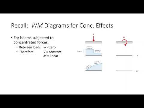
- For concentrated-force and concentrated-moment virtual structures, moment diagrams are linear, and their functions can be obtained from the shear-based slope and a known point.
- For the 15 ft cantilever carrying 2.5 kip/ft, the real moment function is M(x) = -1.25x² kip-ft over 0 to 15 ft.
- With E = 20,000 ksi and I = 1,500 in⁴, the worked example gives a downward tip displacement of 0.911 in and a counterclockwise rotation of 0.387 degrees.
- When moment and length inputs are in kip-ft and feet but EI is inch-based, use 1728 for displacement; use 144 times 180/pi for rotation in degrees.
Chapters
0:00
Course Updates and the Beam-Deflection Homework Schedule
- Gregory Michaelson says Project 1 grading is underway, with the goal of finishing before Exam 2.
- Homework 5.7 on frame shear and moment diagrams was due that day.
- The beam-deflection assignment is due Friday; the next assignment, Homework 6.2, is longer and due Wednesday after tips on Monday.
2:17
Beam Virtual Work: Integrate Moment Products Over the Span
- Beam deflection uses the virtual-work expression based on integrating little m times big M over EI, rather than summing member terms as in trusses.
- Each beam member needs real and virtual moment functions, with E as Young's modulus and I as the second moment of area.
- For moments in kip-ft, lengths in feet, and EI in inch-based units, displacement uses a 1728 conversion factor; rotation uses 144 times 180/pi to report degrees.
5:27
Identify Moment-Function Intervals by Tracking Load Interruptions
- A new moment function is needed when a moving section cut passes a reaction or where a distributed load starts or ends.
- Michaelson's section-cut method tracks the loads visible to the left as the cut moves from one end of the beam to the other.
- The example beam has three intervals, with moment-diagram shapes described as cubic, parabolic, and cubic.
9:05
Use Shear Diagrams to Write Linear Moment Functions Quickly
- With only concentrated forces or moments, the moment diagram consists of linear regions, making point-slope form a quick way to write moment functions.
- The moment-diagram slope equals the shear, so the shear diagram supplies the line's slope without a separate calculation.
- Virtual structures use concentrated unit loads or moments, so their moment functions are linear; the same shortcut works on any linear region of a real moment diagram.
13:08
Derive the Cantilever's Real Moment Function
- The worked beam is a 15 ft cantilever with a uniform downward load of 2.5 kip/ft; the target is vertical displacement and rotation at free end A.
- A section cut at distance x from the fixed end and viewed from the left encloses a distributed load with resultant 2.5x kip at x/2.
- Moment equilibrium gives the real moment function M(x) = -1.25x² kip-ft, valid from x = 0 to 15 ft.
22:36
Build the Virtual Moment Function for Tip Displacement
- For the displacement at A, remove the real loads and apply a unit downward load at the free end.
- A section cut at x gives a linear virtual moment function with magnitude x, valid over the full 0 to 15 ft span.
- The real and virtual moment functions are then multiplied and integrated as one interval because neither has a load interruption.
29:17
Integrate the Moment Product to Find Tip Displacement
- The product of the moment-function magnitudes is 1.25x³; integrating from 0 to 15 ft gives 12,656.25.
- Using E = 20,000 ksi, I = 1,500 in⁴, and the 1728 displacement conversion yields a downward tip displacement of 0.911 in.
- Once both moment functions are established, the remaining virtual-work calculation is a definite integral with constants factored outside.
37:32
Model the Tip Rotation with a Unit Counterclockwise Moment
- For rotation at A, the virtual structure applies a unit moment at the free end in the assumed counterclockwise direction.
- The corresponding virtual moment function is constant, with magnitude 1 across the 15 ft span.
- The real moment function and beam properties remain unchanged; only the virtual function and rotation unit conversion differ.
42:24
Calculate the Rotation and Interpret Its Sign
- The rotation calculation integrates the x² moment product from 0 to 15 ft, giving 1,125.
- With E = 20,000 ksi, I = 1,500 in⁴, and the 144 times 180/pi conversion, the rotation is 0.387 degrees.
- The positive result means the free-end rotation is counterclockwise, matching the direction of the applied virtual unit moment.
Summary, takeaways, and chapters were generated by AI from the video's transcript and may contain errors. The video belongs to its creator, Gregory Michaelson.