CE 312 Lecture 23: Beam/Frame Deflections I, Differential Equation & USCS Units (2026.10.12)
 Watch on YouTube →
Overview
Gregory Michaelson derives the beam-deflection framework for virtual work, connecting bending moment to curvature through the Euler–Bernoulli relation and showing why variable moment diagrams require integration rather than the member-by-member sums used for trusses. He also establishes practical USCS conversion factors for calculations using moments in kip-ft, Young’s modulus in ksi, and area moments of inertia in in⁴.
Key takeaways
- For trusses with constant axial forces, virtual work is a member-by-member sum; for beams and frames, varying bending moments require integration over each member region.
- The beam-deflection relation v″ = M/EI follows from M = EI/ρ after using the small-slope approximation, and is also called Euler–Bernoulli beam theory or the moment-curvature equation.
- A virtual unit force at the target point finds displacement in its direction, while a virtual unit moment finds rotation in its assumed direction.
- The beam/frame virtual-work calculation is ∫m(x)M(x)/(EI) dx, where M is the real moment function and m is the virtual moment function.
- With kip-ft moments, E in ksi, and I in in⁴, multiply the computed deflection by 1728 to report inches.
- With the same USCS conventions, multiply the computed rotation by 144 × 180/π to report degrees; omitting 180/π leaves the result in radians.
Chapters
0:00
Course Schedule, Exam 2, and Beam-Deflection Assignments
- Exam 2 is scheduled for Monday, October 26, and the next five lectures focus on beam deflection.
- Homework 6.2 is described as the semester’s longest assignment; Monday’s lecture will offer virtual-work strategies for beams and frames.
- Homework 6.3 is a Mastan installation check requiring a screenshot; in-class Mastan demonstrations follow Exam 2.
5:05
From Truss Virtual Work to Integrating Variable Beam Forces
- Truss virtual work uses two analyses: original loads produce real member forces, and a unit load at the target joint produces virtual forces.
- The truss displacement sum uses virtual force × real force × member length divided by EA, with lengths converted to inches when E is in ksi and A is in in².
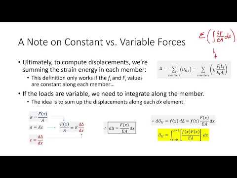
- Beam and frame forces vary along members, so their energy contributions must be integrated; the general axial-work form is ∫fF/(EA) dx.
15:27
Area Integrals, Section Properties, and Curvature Notation
- Michaelson introduces shorthand for area integration: ∫ over an area uses da to represent a small area element.
- First moments of area, ∫y da and ∫x da, locate the centroid; second moments such as ∫y² da define the area moment of inertia.
- For a deflection curve, the first derivative gives slope, the second derivative gives concavity, and curvature is y″/[1+(y′)²]^(3/2).
21:30
Beam-Bending Assumptions and Strain from Curved Layers
- The derivation assumes linear-elastic behavior, no permanent deformation, and small deflections that do not materially change equilibrium.
- The neutral axis through the centroid is treated as unchanged in length, while fibers above and below it compress or stretch.
- For a curved beam segment, the neutral-axis arc length is ρθ and a fiber offset by y has length (ρ−y)θ, yielding bending strain proportional to y/ρ.
27:33
Cross-Sectional Moment Equilibrium Produces M = EI/ρ
- Bending stress varies linearly with distance y from the centroid and is related to strain through Young’s modulus E.
- A small cross-sectional area element contributes a force equal to stress times area and a moment equal to that force times its lever arm y.
- Integrating those contributions across the section introduces I = ∫y² da and leads to the moment-curvature relation M = EI/ρ.
30:13
Euler–Bernoulli Beam Equation and Small-Slope Approximation
- Since curvature is 1/ρ, the section result gives curvature = M/EI.
- With small deflections, the slope is small, so the curvature denominator is approximated as one and the relation becomes v″ = M/EI.
- This Euler–Bernoulli, or moment-curvature, differential equation is foundational, although the lecture computes deflections with virtual work instead of solving it directly.
32:52
Virtual Unit Loads and the Beam-Frame Deflection Integral
- The real analysis retains the original loads; the virtual analysis applies a unit force at the point and in the direction of a desired displacement.
- To find rotation, apply a unit moment in the assumed rotational direction; a positive result confirms the assumption and a negative result reverses it.
- Combining real and virtual moment functions gives displacement or rotation as a sum of integrals, ∫m(x)M(x)/(EI) dx, over the member regions.
38:23
USCS Dimensional Analysis for Rotations and Deflections
- The intended working units are force in kips, length in feet, bending moment in kip-ft, E in ksi, and I in in⁴.
- Under that convention, the rotation calculation carries ft²/in²; multiplying its numerical result by 144 converts the ratio to a radian measure.
- To report rotations in degrees, multiply by 144 × 180/π; to report deflections in inches, multiply by 1728.
45:30
Key Formulas and Preview of Worked Beam Examples
- Michaelson highlights the virtual-work integral and the two USCS conversion factors—1728 for deflections and 144 × 180/π for rotations—as the main application takeaways.
- The upcoming examples progress from beams with one moment-function region on Wednesday to multiple regions on Friday.
- The lecture closes by emphasizing a step-by-step practice sequence rather than requiring students to master the derivation immediately.
Summary, takeaways, and chapters were generated by AI from the video's transcript and may contain errors. The video belongs to its creator, Gregory Michaelson.